


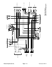
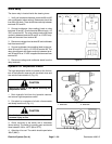

Reelmaster 4000–D Page 5 – 19 Electrical System (Rev. A)
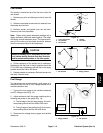
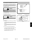
Hour Meter
IMPORTANT: Make sure to observe polarity on the
meter label when testing. Damage to the meter may
result from an improper connection.
1. Connect the positive (+) terminal of a 12 VDC
source to the positive terminal of the hour meter.
2. Connect the negative (–) terminal of the voltage
source to the negative terminal of the hour meter.
3. The meter should move 1/10 hour in 6 minutes.
4. Disconnect the voltage source from the hour meter.
Figure 6
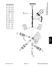
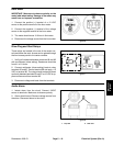
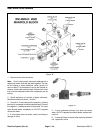
Glow Plug and Start Relays
These relays are located in the rear of the center con-
sole and below the seat. Access can be gained through
the front access panel to the center console.
1. Verify coil resistance between terminals 86 and 85
with a multimeter (ohms setting). Resistance should be
from 41 to 51 ohms.
2. Connect multimeter (ohms setting) leads to relay
terminals 30 and 87. Ground terminal 86 and apply +12
VDC to terminal 85. The relay should make and break
continuity between terminals 30 and 87 as 12 VDC is ap-
plied and removed from terminal 85.
3. Disconnect voltage and leads from the terminals.
Figure 7
86 87
85 30
30
87
85 86
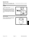
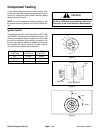
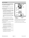
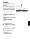
Audio Alarm
1. Isolate alarm from the circuit. Connect 12VDC
source to terminals. Make sure to observe polarity.
2. Alarm should sound. Remove voltage source from
the alarm. Reconnect alarm to the circuit.
1. Top view 2. Side view
Figure 8
2
1
Electrical
System