


Reelmaster 4000–D
Page 4 – 15
Hydraulic System
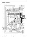
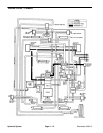
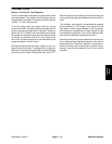
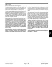
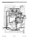
Lift/Lower Circuit
Refer to “Lift Circuit” Flow Diagrams
The lift cylinders are controlled by an open center valve
with three spools. The number 4 and 5 cutting units are
independently controlled. The center spool controls the
number 1, 2, and 3 cutting units.
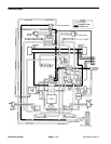
To lift the cutting units, the engine must be running
above half throttle. The flow of oil from the steer and lift
pump is used to accomplish the lift function. Holding a
lever in the “LIFT” position will direct the flow of oil to the
lift cylinder and raise the cutting unit. Oil pressure to the
lift cylinder is monitored during LIFT by a relief at the
valve inlet. System pressure may be monitored at the
pressure tap port on the lift valve.
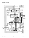
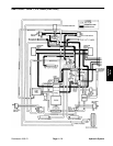
Moving the lever forward will open a path for oil to es-
cape from the lift cylinder. The weight of the cutting unit
will push oil from the cylinders through the valve allowing
the cutting unit to lower. Moving the lever into “LIFT”
while the cutting unit is lowering will lock the cutting unit
at any position by trapping oil between the valve and cyl-
inder.
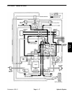
The cylinders work against counterbalance pressure
during lowering. For this reason, the cutting units will
drop faster at slow engine speeds or low counterbal-
ance pressures compared to full engine speed or high
counterbalance pressures. The counter balance pres-
sure may be monitored at pressure tap port 3.
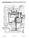
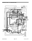
Since the lift levers are spring loaded from return to neu-
tral, a detent plunger latches the spool in the valve to
hold the spool in a “Free Float” position. The position en-
ables the cutting units to follow ground contours by al-
lowing a two–way flow between the lift valve and lift
cylinders.
Hydraulic
System