


Reelmaster 4000–DPage 7 – 16Cutting Units
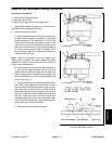
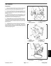
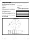
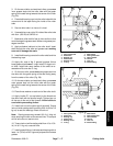
Roller Bearing Replacement
1. Roller tube (front roller shown)
2. Roller shaft
3. Grease fitting
4. Lock nut
5. Jam nut
6. Trust washer
7. Outer grease seal
8. Wear sleeve
9. O–ring
10. Bearing cone
11. Bearing cup
12. Inner grease seal
Figure 28
4
7
9
11
3
6
8
10
12
1
2
6
5
12
11
10
9
8
7
Removal
1. Clean roller around the shaft, grease fittings, and
bearing thoroughly. Both ends of the roller should be
free of dirt and debris.
2. Secure roller tube in a vise keeping it level.
3. Remove both grease fittings before removing the
bearings.
4. Remove jam nut, lock nut, and both thrust washers
from the roller shaft. Pull both outer grease seals from
inside the roller tube.
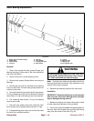
5. Use a soft hammer to pound the shaft, wear sleeve,
O–ring, and bearing cone out of the roller tube. Remove
wear sleeve, O–ring, and bearing cone from the shaft.
6. Pull remaining wear sleeve, O–ring, and bearing
cone from the roller.
7. Pull both inner grease seals from inside the roller
tube. Discard all four grease seals and both O–rings.
8. If disassembling a rear roller, pour oil from the inside
the roller into a suitable container.
WARNING
If removing bearing cups from a rear roller with
an arc welder, make sure the entire roller is free of
oil. Clean inside and out side thoroughly.
Note: An electric arc welder can be used to shrink the
bearing cup to simply its removal. Only a small arc in one
location on the cup is required.
9. Remove both bearing cups from the roller tube.
Installation
IMPORTANT: Replace both bearing cones and cups
with new ones, since both bearing cones and cups
may be damaged during removal.
1. Make sure all parts are cleaned thoroughly. Inside
of roller tube should be free of dirt and debris.
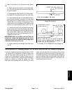
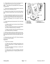
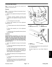
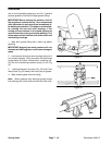
2. On the front roller, press new inner grease seals into
the roller tube with the garter spring of the seal facing
away from the center of the roller (Fig. 29).