


Reelmaster 4000–DPage 5 – 28Electrical System (Rev. A)
Hydraulic Oil Filter Switch
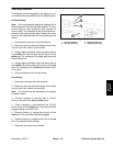
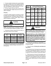
The oil filter switch is activate by the differential pressure
across the oil filter. When differential pressure is be-
tween 16 to 20 PSID, a normally open contact closes. An
alarm sounds and a warning light comes on at the instru-
ment panel. When the differential pressure drops be-
tween 16 to 12 PSID the switch contact opens and the
alarm and light go out.
The purpose of the oil filter switch, warning light, and
alarm is to detect a clogged oil filter. When the hydraulic
oil is cold (below 68
o
F/15
o
C), the oil is thicker and
causes a greater pressure drop across the filter. This sit-
uation will cause the oil filter warning alarm and light to
come on. Push the silence button until the hydraulic oil
warms up. The warning light will stay on until the oil
warms up (about 5 to 15 minutes).
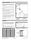
Checks
1. Turn off engine. Disconnect electrical connector
from the oil filter switch. Check continuity across the
switch. The switch should indicate open.
2. If continuity across the switch indicates open, the
switch is good,
A. Check that the oil filter element or filter head is
not clogged.
B. Check circuitry to the alarm and warning light for
for possible faults.
WARNING
Before disconnecting or performing any work
on hydraulic system, all pressure in system
must be relieved by stopping the engine and
lowering or supporting the box and/or other at-
tachment.
Keep body and hands away from pin hole leaks
or nozzles that eject hydraulic fluid under high
pressure. Use paper or cardboard, not hands,
to search for leaks. Hydraulic fluid escaping
under pressure can have sufficient force to
penetrate the skin and do serious damage. If
fluid is injected into the skin, it must be surgi-
cally removed within a few hours by a doctor
familiar with this type of injury or gangrene
may result.
3. If continuity across the switch indicates closed, Re-
move and replace switch with a new one.
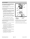
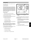
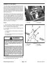
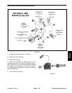
1. Filter head 2. Filter element
Figure 25
1
2
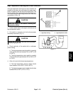
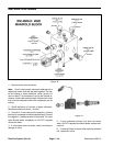
1. Filter switch
2. O–rings
3. Filter head
4. Filter element
Figure 26
1
2
4
3