


Reelmaster 4000–D
Page 4 – 77
Hydraulic System
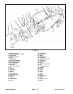
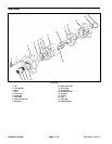
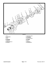
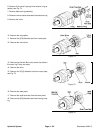
Disassembly of Reel Pump
During disassembly, pay particular attention to identifi-
cation of the parts for correct assembly.
1. Clamp the port section (13) in a vise with protective
jaws to avoid damage to the port section’s machined
surfaces.
2. Remove gear coupling (14) from port section (13).
3. Remove eight nuts (1) and eight washers (2).
4. Remove front cover (4) from wear plate (7).
5. Remove seal retainer (6) and gland seal (5) from front
cover (4) and discard.
6. Remove wear plate (7) from center section (8).
7. Remove spline drive gear (10) and driven gear (11)
from center section (8).
8. Removal of the center section (8) may require the use
of a plastic hammer.
9. Remove wear plate (7) from port section (13).
10. Remove seal retainer (6) and gland seal (5) from
port section (13) and discard.
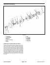
Inspection of Reel Pump
All parts must be thoroughly cleaned and kept clean dur-
ing inspection and assembly. The close tolerance of the
parts makes this requirement very important. Paint
found on the edges of all parts must be removed. Clean
all removed parts, using a commercial solvent that is
compatible with the system fluid. Compressed air may
be used in cleaning, but it must be filtered to remove wa-
ter and contamination.
New seal kits (5 & 6) are required for assembly. Wash
the metal parts, blow dry them with air, and place on a
clean surface (Kraft paper) for inspection.
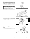
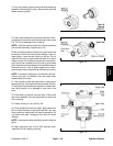
1. Place front cover S/A (4) in a vise (mounting flange
up). Using a screwdriver, pop out the outer shaft seal (9),
being careful not to raise a burr on the shaft seal bore.
2. Remove the retaining ring (18) with internal retaining
ring pliers.
3. Remove front cover S/A (4) from vise and place on
work bench with mounting flange down. Using a bronze
drift and hammer, drive inner shaft seal (17) out through
mounting flange, being careful not to damage bearing.
4. Inspect the drive and driven gear bushings of front
cover (4) for pickup, scoring, discoloration, or excessive
wear. Any of the preceding conditions shall warrant re-
placement of the front cover S/A (4). Inspect mounting
flange for nicks and burrs. Remove with India stone.
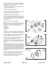
5. Inspect wear plates (7) for erosion, pitting, scratching,
an/or scoring. Replace if necessary.
6. Inspect the center S/A section (8) for porosity, cracks,
and scratches (.010 or deeper). Replace if necessary.
DO NOT deburr the figure eight section of the center
section.
7. Inspect splines on the drive gear (10) and driven gear
(11) for nicks or excessive wear. Inspect gear journals
fro scratches and discoloration.
Any discoloration war-
rants replacement
. Inspect gear teeth for spalling,
scratches, and/or excessive wear. Replace if necessa-
ry. Stoning teeth to remove burrs is permissible. The
face of the gear teeth should also be inspected for
scratches.
8. Inspect the drive and driven gear bushings on the port
section (13) for pickup, scoring, discoloration, and/or
wear.
Any of the preceding conditions shall warrant re-
placement of the port section
. Inspect inlet flange for
nicks and burrs. Stone to remove. Inspect studs (3) for
cross threads, cracks, and burrs. if studs are defective,
remove as follows: Install a nut (1) on the stud as far as
possible. Then install another nut over the first one and
tighten to lock in place. Apply torque to the first nut and
remove the stud. Refer to the parts drawing for stud part
numbers and installation instructions
Hydraulic
System