


Reelmaster 4000–D Page 7 – 13 Cutting Units
Assembly
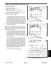
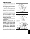
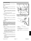
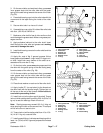
1. Inspect flange bushings in the mounting holes of the
drive housing and bearing housing for wear (Fig. 21).
Replace, if necessary.
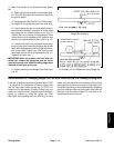
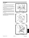
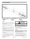
2. Assemble outer seal (lip facing in to retain grease)
into the drive housing using Loctite 242 (or equivalent)
retaining compound on the outer diameter. Apply a light
coat of oil to the seal lips and insert the bearing assem-
bly through the seal from the opposite side (Fig 23).
3. Apply a light coating of oil to the inner seal lips and
install (lip facing away from the bearing and toward the
reel) in the housing. Install retaining ring to secure the
assembly in the housing (Fig. 23).
4. Apply a light coat of oil to the seal lips of the seal for
the bearing housing and install (lip facing away from the
bearing) over the bearing assembly (Fig. 23).
5. Insert bearing and seal in the housing and install the
dust cap into the housing.
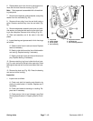
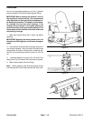
6. Assemble reel assembly to the frame. Ensure
shield washer is installed on the drive housing end of the
reel shaft. Align drive pin on reel shaft with slot in bearing
and slide the drive housing onto the shaft.
7. Insert shoulder bolt through the Belleville washer
and rear housing mounting hole. Slide bolt through the
side plate mounting hole (Fig. 21). Install the cone nut
locknut onto the bolt. Tighten the cone nut to 45 to 55 ft–
lbs (6.2 to 7.6 kg–m).
8. Align the drive pinon the reel shaft with the notch in
the bearing inner race and slide the bearing housing
over the opposite end of the reel shaft. Insert the shoul-
der bolt and belleville washer through the rear bearing
housing mounting hole. Slide the bolt through the side
plate mounting hole. Install the cone onto the bolt. Tight-
en the cone nut to 45 to 55 ft–lbs (6.2 to 7.6 kg–m).
Figure 24
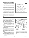
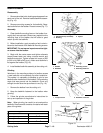
9. Install woodruff key in the drive housing end of the
reel shaft and install the driven pulley onto the shaft.
10. Ensure slot in the pulley washer is aligned with the
roll pin in the pulley and install the washer, toothed
washer and reel capscrew (Fig. 22). Apply a medium
strength thread locking compound to the reel capscrew
during assembly. Torque the capscrew to 45 to 55 ft–lb
(6.2 to 7.6 kg–m).
11. Install reel adjustment assemblies to each side
plate. Install roll pins before tightening fasteners.
12. Install bedbar/bedknife assembly.
13. Install front and rear roller assemblies or skids.
14. Adjust reel to the bedknife (see Reel to Bedknife.
Adjust height–of–cut (see Adjust Height–of–Cut).
Cutting Units