


Reelmaster 4000–DPage 7 – 14Cutting Units
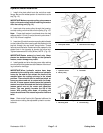
Preparing a Reel for Grinding
Note: Check to make sure the reel bearings are in
good condition before grinding the reel. Make sure the
cutting unit frame and roller brackets are true and not
bent or damaged.
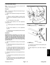
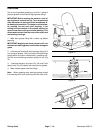
1. Remove the bedbar assembly (Bedknife/Bedbar
Disassembly).
2. Remove parts as necessary to mount the cutting
unit into the grinder (e.g., front roller, front roller brack-
ets).
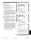
3. Follow the grinder manufacturer’s instructions for
set–up and operation of the grinder.
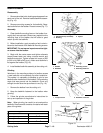
Note: The cutting unit must be aligned so the grinding
wheel will travel parallel to the reel shaft. This will result
in the reel being ground to the desired cylinder shape.
Note: When grinding, be careful to not overheat the
reel blades. Remove small amounts of material with
each pass of the grinder.
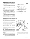
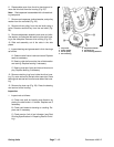
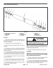
4. After completing the grinding process:
A. Install parts that were removed to mount the cut-
ting unit onto grinder.
B. Install bedbar assembly (see Bedknife/Bedbar
Assembly).
C. Do a complete cutting unit set–up and adjust-
ment procedure (see Adjustments section).
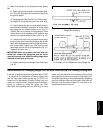
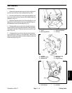
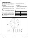
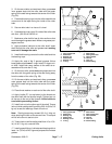
Reel Grinding Specifications
Nominal Reel Diameter
8 in (206 mm)
Service Limit Reel Diameter 7.2 in (182 mm)
Blade Relief Angle 30
o
Relief Angle Range 20
o
to 40
o
Blade Land Width
0.060 in (1.5 mm)
Land Width Range 0.050 to 0.090 in (1.3 to 2.3 mm)
Max. Reel Taper 0.060 in (1.5 mm)
REEL DIAMETER TAPER = D
1
– D
2
D
1
D
2
BLADE RELIEF ANGLE
REEL DIAMETER
BLADE
LAND
WIDTH
Figure 25