


Reelmaster 4000–D
Page 4 – 79
Hydraulic System
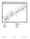
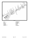
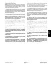
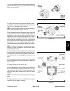
Reassembly of Reel Pump
NOTE: Coat all parts with clean hydraulic fluid to facili-
tate assembly and provide initial lubrication. Use small
amount of petroleum jelly to hold seal glands (5) and re-
tainers (6) in place during assembly.
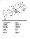
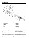
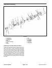
1. Assemble seal packs by inserting the seal glands (5)
into the seal retainers (6). Install a seal pack into the cav-
ity located on the face of the port section (13) with the
seal retainer pointing up.
2. Place port section (13) in vise with studs (3) facing up.
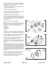
NOTE: The next five steps pertain to installation of front
cover shaft seals (9 & 17). Lubricate the shaft seals with
Marfak grease to provide initial lubrication.
3. Install inner shaft seal (17) into front cover (4). Make
sure the spring loaded member of shaft seal faces the
inside of pump. Place the shaft seal (17) on shaft seal
driver and press in place.
4. Install retaining ring (18) into front cover on top of
shaft seal (17).
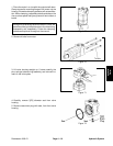
5. Place a guide over the pilot diameter of front cover (4).
6. Install a new outer shaft seal (9) on the driver. Make
sure the spring loaded member of shaft seal faces the
inside of pump.
7. Insert the driver and shaft seal though the guide and
press in place.
8. Place wear plate (7) on port section (13) with bronze
face up and notch facing inlet port.
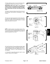
9. Lubricate bronze face of wear plate (7). Install center
section (8) on top of wear plate (7) and into locating
holes of port section (13) with major diameter facing port
section and notch facing inlet port. Make sure wear plate
and center section set flush against port section.
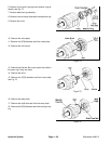
10. Tape the spline area (long spline) of drive gear (10)
to prevent cutting shaft seal(s) during assembly.
11. Lubricate drive gear (10) and driven gear (11). Install
drive gear (10) into port section (13) with short spline to-
wards port section. Install driven gear (11).
12. Lubricate bronze face of wear plate (7). Install wear
plate (7) over locating pins of center section (8) with
bronze face towards center section and notch facing in-
let port.
13. Install seal pack (5 & 6) into cavity located on face
of front cover (4). Apply petroleum jelly around seal pack
area on face of front cover.
14. Carefully position front cover (4) over studs (3),
gears (10 & 11), and center section guide pins. Gently
slide front cover over the gears until it is flush against
wear plate (7).
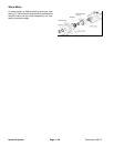
15. Lubricate stud (3) threads with hydraulic fluid. Install
washer (2) and nuts (1) on ends of studs. Cross torque
nuts to 60 to 70 ft–lb.
16. Clamp port section (13) into vise with studs facing
down. Make sure port section is clamped securely.
17. Install O–ring (15) into groove located on face of port
section (13).
18. Install lubricated coupling (14) on spline of drive
gear (10).
19. Turn the drive gear (10) one revolution with a suit-
able socket wrench. Not binding shall be evident during
this operation. The breakaway torque necessary to turn
the drive gear must not exceed 140 in–lb.
Hydraulic
System