


Reelmaster 4000–D
Page 4 – 19
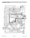
Hydraulic System
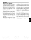
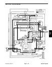
Reel Circuit
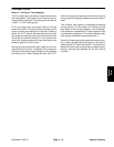
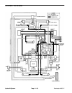
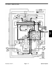
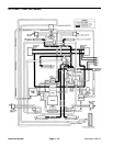
Refer to “Reel Circuit” Flow Diagrams
The three reel shut–off valves in this circuit enable the
cutting units to be operated in several configurations for
easier control, better clearance, or closer trimming.
The reel pump supplies a constant flow of oil to the reel
speed control valve. The reel speed is variable and ad-
justable by the operator to supply a flow of oil to the reel
“On–Off” valve. Oil not needed to obtain the selected
reel speed is directed back to the sump tank through the
drain block, oil cooler, and filter.
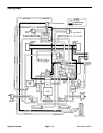
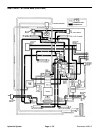
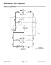
When the reel “On–Off” valve lever is moved into “Mow”
to engage the reels, a spool in the valve is shifted to di-
rect oil to the shut–off valve at the front of the unit. With
the Number 1, 2, and 3 cutting units in mowing position,
the shut–off valve will allow oil to flow to the Number 2,
3, and 1 reel motors. The oil is also available for use at
the Number 4 shut–off valve. If the Number 1, 2, and 3
cutting units are in the raised position, the oil will bypass
these motors and be available directly to the Number 4
shut–off valve.
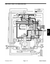
With the Number 4 cutting unit in the down and mowing
position, the Number 4 shut–off valve will allow the oil
through to drive the reel motor and then to the Number
5 shut–off valve. If the Number 4 cutting unit is in the
raised position, the oil will bypass the Number 4 reel mo-
tor and be available directly to the Number 5 shut–off
valve.
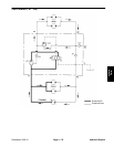
With the Number 5 cutting unit in the down and mowing
position, the Number 5 shut–off valve will allow the oil
through to drive the reel motor. If the Number 5 cutting
unit is in the raised position, the oil will bypass the Num-
ber 5 reel motor and return to the reel “On–Off” valve.
From the reel “On–Off” valve, the oil returns to the sump
tank through the drain block, oil cooler, and filter.
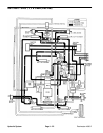
“Backlap” is provided by pulling the reel “On–Off” valve
lever up and back. The backlap function requires that
the lever be held in this position for safety. The direction
of flow in “Backlap” is the opposite of “Mow”. Some units
will include a low–speed backlap valve in the circuit to
remove some oil flow from the circuit during the backlap
function. The reduced oil flow results in a slower reel
speed in “Backlap”, but does not affect performance
during “Mow”.
System pressure may be monitored at pressure tap 4 for
either “Mow” or “Backlap”.
Hydraulic
System