


Reelmaster 4000–D Page 3 – 15 Kubota Diesel Engine
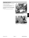
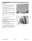
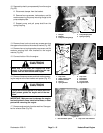
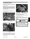
12. Separate hydraulic pump assembly from the engine
(Fig. 25).
A. Disconnect damper from the bracket.
B. Remove four cap screws, lock washers, and flat
washers securing the pump mounting flange to the
pump adapter plate.
C. Support pump, and pull pump shaft from the
spring coupling.
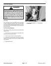
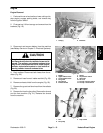
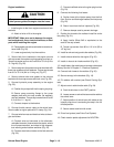
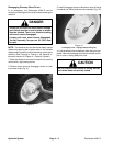
13. Remove three lock nuts and cap screws securing
the upper exhaust tube to the exhaust bracket (Fig. 26).
14. Remove hex nut, spring washer, cap screw, and flat
washers securing both front brackets to the engine
mounts (Fig. 26).
15. Connect hoist or lift to the engine.
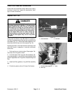
CAUTION
Make sure lift or hoist can support the total
weight of the engine before removing the cap
screws from the rear bracket and engine.
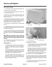
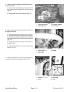
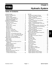
16. Remove three cap screws and lock washers secur-
ing the engine to the rear bracket and spacer (Fig. 27).
CAUTION
One person should operate lift or hoist while the
other person guides the engine out of the ma-
chine.
IMPORTANT: Make sure not to damage the engine,
fuel and hydraulic lines, electrical harness, or other
parts while removing the engine.
17. Remove engine slowly from the machine. Save gas-
ket for exhaust tube (Fig. 26).
Figure 25
1. Damper
2. Bracket
3. Pump mounting flange
4. Pump adapter plate
5. Spring coupling
4
3
1
2
5
4
Figure 26
1. Cap screw
2. Upper exhaust tube
3. Exhaust bracket
4. Hex nut
5. Spring washer
6. Cap screw
7. Flat washer
8. Flat washer
9. Front bracket
10. Engine mount
1
1
3
2
6
8
7
5
9
4
9
10
Figure 27
1. Rear bracket & spacer 2. Cap screw & lock washer
1
2
Kubota Diesel
Engine