


Reelmaster 4000–D
Page 4 – 69
Hydraulic System
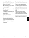
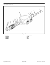
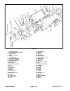
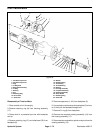
Disassembly of Traction Pump
1. Disconnect all control linkage, hydraulic lines and re-
move pump assembly from vehicle.
2. Plug all ports and thoroughly clean outside of pump.
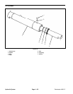
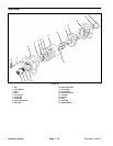
3. Clamp the end of the drive shaft in a protected jaw
vise with the body of the pump up and remove the four
cap screws (1 & 36) from the adapter plate of the pump.
4. Use a plastic mallet and tap the charge pump adapter
(2) to loosen it, then pull the adaptor straight up until it
is free.
5. Remove spring retainer (44) and remove spring (43)
and poppet (42) from adaptor assembly (2).
6. Remove the gerotor gear (7) and key (35) from the
pump shaft.
7. Remove the two check valve assemblies (8) from
back plate (9). Pin is loose fitting. Caution should be tak-
en when removing check valve assembly so that pin and
ball are not lost.
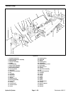
8. Use screwdriver slots in housing and pry up on back
plate (9) or tap with plastic mallet to loosen, then pull the
back plate straight up to remove. Remove housing gas-
ket (10).
9. Remove the tow valve (4) from back plate (9). To dis-
assemble tow valve, remove retaining ring from spread-
er, and pull spreader from spreader plug.
10. Remove plug assembly (3), spring (41) and relief
valve assembly (34) from back plate.
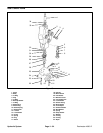
11. Remove pump from vise and remove rotating kit as-
sembly (12) from housing (19).
12. If pistons did not come out with piston block, you
may remove them, spider, and spider pivot.
IMPORTANT: Do not attempt to disassemble the
piston block and spring. The parts are not service-
able separately. The rotating kit (12) must be re-
placed as an assembly.
13. Remove retaining ring (25) from housing. Press
drive shaft (31) from housing (19) and remove shaft seal
(26) and washer (27).
14. Remove retaining ring (28) from shaft and remove
thrust race (29) and thrust bearing (30).
15. To remove the camplate (14) from housing, remove
screws (24) from the sides of the housing. Remove trun-
nion cover (23), seal cover (15), O–ring cover (22), O–
ring (21), washer (17), inner race (20), and needle
bearing (18). Remove shaft seal (16), washer (17), and
needle bearing (18).
Hydraulic
System