


Reelmaster 4000–DPage 5 – 26Electrical System (Rev. A)
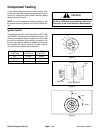
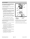
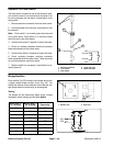
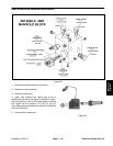
Hydraulic Oil Level Switch
The level switch is located on top of the hydraulic reser-
voir under the seat. It has an electrical connector from
the wiring harness with two black, a black/white, and a
orange wire.
1. Remove electrical connector from the level switch.
2. Unscrew sender from the cover, and remove it from
the reservoir.
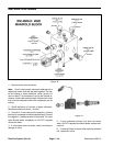
Note: Float switch L1 is normally open when the tank
is dry (float down). Float switch L2 is normally closed
when the tank is dry (float down).
3. Position float switch L2 against its lower float stop.
4. Check for continuity between electrical connector
leads associated with the yellow wires.
5. Position float switch L2 against its upper float stop.
6. Check continuity between electrical connector
leads associated with the yellow wires. There should be
no continuity between connector leads.
7. Replace switch as necessary. Install switch to hy-
draulic reservoir.
1. Electrical connector
2. Level switch
3. Float switch
4. Lower float stop
5. Upper float stop
Figure 21
4
5
2
1
L2
L1
L2
L1
RED
RED
YELLOW
YELLOW
3
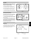
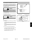
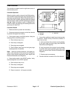
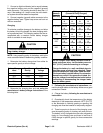
Bridge Rectifier
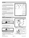
Each rectifier (Fig. 22) contains four diodes which form
a single phase bridge rectifier circuit (Fig. 23). The
diodes are used for circuit protection from inductive volt-
age spikes when the alarm relay is deenergized.
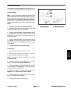
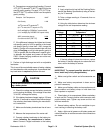
Testing
The diodes can be individually tested using a digital
multimeter (ohms setting) and the table below.
Red Lead (+)
on Terminal
Black Lead (–)
on Terminal
Continuity
AC1 + YES
+ AC1 NO
AC2 + YES
+ AC2 NO
– AC1 YES
AC1 – NO
– AC2 YES
AC2 – NO
1. Bottom view 2. Side view
Figure 22
2
2
Figure 23
AC1
AC2