


Workman MD/MDX
Drive Train
Page 5 -- 18
IMPORTANT: Take care to not damage the engine,
fuel hoses, electrical harness or other parts while
lowering the engine tray assembly.
13.Carefully move engine tray assembly toward therear
of the vehicle to clear mounts on swing arm. Then, lower
engine tray enough to allow the transaxle and driven
clutch to be removed from the rear of the vehicle. Sup-
port engine tray in this position to prevent it from shifting
or falling.
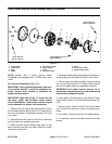
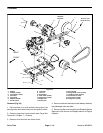
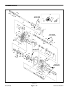
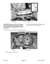
14.Remove four (4) flange nuts (item 12) and flange
head screws (item 16) that secure the transaxle to the
engine tray.
15.Carefully remove transaxle assembly from the rear
of the vehicle.
Installation (Fig. 22)
1. Position transaxle assembly to the engine tray. Se-
cure transaxle to the tray with four (4) flange nuts (item
12) and flange head screws (item 16).
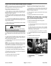
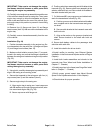
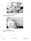
2. Make sure that isolation mounts (item 17) are posi-
tioned in the s wing arm so that the flange is positioned
between the swing arm bracket and engine tray location
(Fig. 25).
IMPORTANT: Take care to not damage the engine,
fuel hoses, electrical harness or other parts while
raising the engine tray assembly.
3. Using hoist, carefully raise engine tray assemblyand
align it with swing arm mounting points.
4. Secure the transaxle to the swing arm with four (4)
cap screws (item 3) and flat washers (item 2).
5. Secure engine tray to the swing arm:
A. Align engine tray to swing arm. Insert cap screw
with flat washer up through swing arm bracket, isola-
tion mount and engine tray (Fig. 25).
B. Secure cap screw with flange nut.
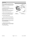
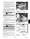
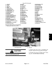
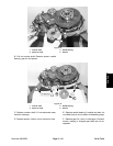
6. Position select lever assembly and shift cables to the
transaxle (Fig. 24). Secure select lever assembly to the
selector shaft with lock nut. Secure both shift cables to
the cable bracket with jam nuts.
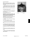
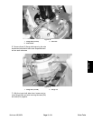
7. On Workman MD, secure governor and cable brack-
ets to the transaxle as follows (Fig. 23).
A. Position governor and cable brackets with cables
as a complete unit to the transaxle case and gover-
nor shaft.
B. Secure cable bracket to the transaxle case with
both lock nuts.
C. Align scribe marks on the governor bracket and
shaft. Secure bracket to the shaft with both s et
screws.
8. Secure both battery cables to the passenger side
axle tube with cable ties.
9. Install drive belt to the driven clutch.
10.Install muffler to machine (see Exhaust System
Installation in the Service and Repairs section of Engine
Chapter).
11.Install both brake assemblies and wheels to the
transaxle (see Rear Wheel and Brake Installation in
Chapter 7 -- Chassis).
12.Install cargo box to the frame (see Cargo Box Instal-
lation in Chapter 7 -- Chassis).
13.Verify proper ground speed (see Adjust Ground
Speed in the Adjustments section of this chapter).
14.Check brakes for proper operation.