


Workman MD/MDXPage 6 -- 12Electrical System
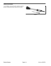
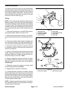
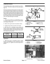
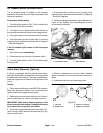
Accelerator Switch
The accelerator switch is a four (4) terminal, two (2) cir-
cuit switch. The switch is attached to the pedal support
(Fig. 11).
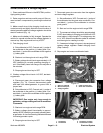
When the accelerator pedal is pushed, the switch allows
current flow to the start/run solenoid, hour meter and en-
gine oil indicator and also provides an open circuit to the
engine ignition system to allow the magneto ignition to
operate. With the accelerator pedal released, the switch
provides a grounding circuit for the engine ignition sys-
tem and also prevents current flow to the start/run sole-
noid, hour meter and engine oil indicator.
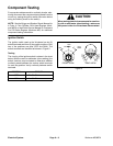
Testing
1. Place machine shift lever in the NEUTRAL position.
Turn ignition switch off, remove key from ignition switch
and engage parking brake.
2. Raise hood to gain access to accelerator switch.
3. Unplug wiring harness connector from switch.
4. With the use of a multimeter (ohms setting), the
switch functions may be tested to determine whether
continuity exists between the switch terminals for both
switch positions. Verify continuity between switch termi-
nals using the following table:
PLUNGER
POSITION
CONTINUITY
NO
CONTINUITY
IN 1 and 2 3 and 4
OUT 3 and 4 1 and 2
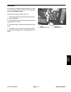
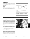
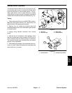
Adjustment
1. Adjust cap screw on accelerator pedal so switch
plunger is not bottomed out when accelerator pedal is
released (Fig. 13). Tighten nut to secure cap screw in
position.
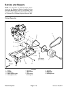
1. Pedal support
2. Accelerator pedal
3. Nut
4. Cap screw
5. Accelerator switch
6. Plate
7. Cap screw (2 used)
Figure 11
1
4
2
3
5
6
7
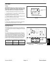
1. Terminal 1
2. Terminal 2
3. Terminal 3
4. Terminal 4
5. Switch plunger
6. Mounting tab
Figure 12
END VIEW
SIDE VIEW
1
6
4
3
2
6
5
SWITCH
SWITCH
1. Accelerator switch 2. Adjustment screw
Figure 13
1
2