


Rev. A13.4
Workman MD/MDX Drive Train
Page 5 --
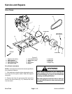
Drive Clutch Inspection
NOTE: Ifdrive clutch wear or damage occurs, clutch re-
placement may be necessary. Refer to your parts cata-
log to identify individual drive clutch components that
are available.
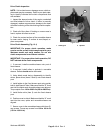
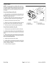
1. Inspect the tapered ends of the engine crankshaft
and fixed sheave of drive clutch. If either is severely
damaged, replace component as damage to the taper
will allow loosening of the clutch during machine opera-
tion.
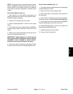
2. Check all of the rollers. If binding or uneven wear is
found, replace all rollers as a set.
3. Check the contact surface of the moveable s heave
for wear and/or fraying. If surface is worn/frayed, re-
place component.
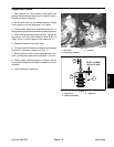
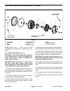
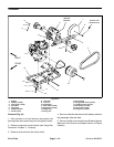
Drive Clutch Assembly (Fig. 19.1)
IMPORTANT: For proper clutch operation, make
sure to use the correct clutch components for your
Workman model and serial number. Do not mix
clutch components from different vehicles.
IMPORTANT: For proper drive clutch operation, DO
NOT lubricate drive clutch components.
1. If removed, install moveable s heave onto post of
fixed sheave.
2. If removed, install rollers to pockets in moveable
sheave. Rollers should not be lubricated.
3. Using labels made during disassembly to identify
shims, place shims (items 3 and 9) onto fixed sheave
post.
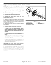
4. Install spider to the fixed sheave post using spider
tool kit (see Special Tools). Make sure that the “X” mark
cast into the spider and moveable sheave are aligned.
Torque spider from 190 to 220 ft--lb (258 to 298 N--m).
5. Install limiter shim (item 2) onto the fixed sheave
post.
6. Position cover to clutch. Make sure that the “ X” mark
cast into the cover, spider and moveable sheave are
aligned.
7. Secure cover to the moveable sheave with three (3)
cap screws. Torque cap screws from 132 to 168 in--lb
(15.0 to 18.9 N--m).
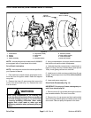
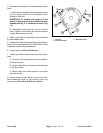
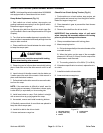
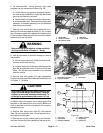
Figure 19.2
1. Holding bar 2. Spanner
1
2
Drive Train