


Workman MD/MDX Page 7 -- 11 Chassis
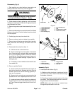
5. Support steering column to prevent it from falling.
Remove four (4) flange nuts and carriage screws secur-
ing the steering column to the mounting plate on the
frame.
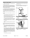
6. Remove dust cover (item 13) from the steering shaft.
Replace cover ifdamaged. Slide steering shaft out ofthe
steering column.
7. Disconnect both tie rods from the Pitman arm on the
steering gearbox (see Lower Steering and Front Wheel
Removal in this section).
8. Remove four (4) c ap screws and lock washers that
secure the steering gearbox to the tower plate on the
front frame. Remove gearbox from the tower plate.
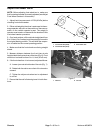
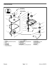
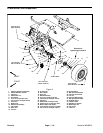
Assembly (Fig. 4)
1. Position steering gearbox to the tower plate of the
front frame with the Pitman arm facing down and to the
rear. The gearbox shaft must be to the left side of the
tower.
2. Secure steering gearbox to the tower plate with four
(4) cap screws and lock washers. Torque screws from
175 to 225 in--lb (20 to 25 N--m).
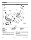
3. Make sure that collar (item 14) is positioned on steer-
ing shaft. Insert steering shaft up through the steering
column.
4. Secure steering column to the mounting plate on the
frame with four (4) carriage screws and flange nuts.
NOTE: Apply antiseize lubricant to the steering gear-
box input shaft before installing to steering s haft
knuckle.
5. Position knuckle of the lower steering shaft onto the
gearbox input shaft. Secure knuckle to the steering
gearbox shaft with cap screw and lock washer.
6. Make sure that collar (item 14) is just below steering
column. If necessary, re--position collar on steering
shaft. Apply Loctite #242 (or equivalent) to collar set
screw and secure collar with set screw.
7. Place dust cover onto the steering shaft.
8. Connect both tie rods to the Pitman arm on the steer-
ing gearbox (see Lower Steering and Front Wheel
Installation in this section).
NOTE: Apply antiseize lubricant to the steering s haft
taper before installing the steering wheel.
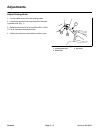
9. Position front tires straight ahead. Slide steering
wheel onto the steering shaft so that the leg of the “Y”
formed by the wheel struts is directed towards the oper-
ator platform.
10.Secure steering wheel to shaft with flat washer and
nut. Torque nut from 18 to 22 ft--lb (25 to 29 N--m).
Install steering wheel cover to wheel.
11.Lower front hood.
12.Check front wheel alignment (see Adjust Front
Wheel Toe--in in the Adjustments section of this chap-
ter).
Chassis