


Workman MD/MDXPage 6 -- 10Electrical System
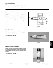
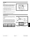
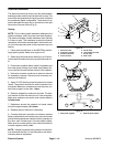
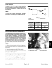
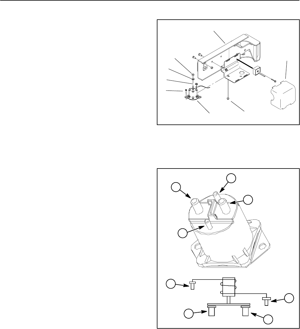
Start/Run Solenoid
The start/run solenoid provides a current path between
starter/generator and the vehicle electrical circuits. This
solenoid is energized when the ignition switch is ON and
the accelerator pedal is depressed. The solenoid is at-
tached beneath the cargo box to a bracket on the right
hand side of the rear frame (Fig. 8).
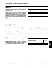
Testing
NOTE: Prior to taking small resistance readings with a
digital multimeter, short the meter test leads together.
The meter will display a small resistance value (usually
0.5 ohms or less). This resistance is due to the internal
resistance of the meter and test leads. Subtract this val-
ue from the measured value of the component you are
testing.
1. Place machine shift lever in the NEUTRAL position.
Apply parking brake. Make sure engine is off.
2. Raise cargo box and secure with prop rod. Gain ac-
cess to start/run solenoid by removing the electrical cov-
er.
3. Disconnect negative (black) cable from battery and
then disconnect positive (red) cable (see Battery Ser-
vice in the Service and Repairs section of this chapter).
4. Note wire connector locations on start/run solenoid
for assembly purposes. Disconnect wire harness con-
nectors from solenoid.
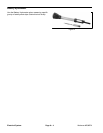
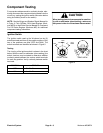
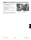
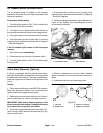
5. Apply 12 VDC directly across the solenoid coil posts
(steel). The solenoid should click as the solenoid coil is
energized. Make sure resistance across the main con-
tact posts (copper) is less than 1 ohm.
6. Remove voltage from solenoid coil posts. The sole-
noid should c lick as the solenoid coil is de--energized.
Make sure resistance across the main contact posts is
infinite ohms.
7. Resistance across the solenoid coil posts (steel)
should be approximately 13.5 ohms.
8. Replace start/run solenoid if necessary.
9. Connect electrical connections to solenoid: positive
battery cable and wire to fuse block on one main contact
post and starter/generator cable andwire to regulator on
the other main contact post. Connect battery cables.
Make sure to connect positive (red) cable first and then
connect negative (black) cable.
NOTE: Voltage is supplied to the solenoid on the Work-
man whenever the key is in the ON position and the ac-
celerator pedal is depressed.
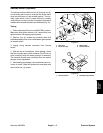
1. Electrical cover
2. Flange nut (2 used)
3. Start/run solenoid
4. Screw (2 used)
5. Nut (2 used)
6. Lock washer (2 used)
7. Nut (2 used)
8. Rear frame
Figure 8
7
4
5
3
2
6
1
8
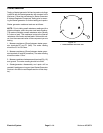
Figure 9
WIRING
DIAGRAM
1. Main posts (copper)
2. Solenoid posts (steel)
1
2
1
1
2
2
2
1