


Workman MD/MDX Page 7 -- 23 Chassis
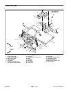
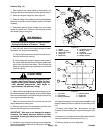
Removal (Fig. 13)
1. Park machine on a level surface, stop engine, set
parking brake and remove key from the ignition switch.
2. Raise and support cargo box with prop rod.
3. Remove muffler from machine (see Exhaust System
Removal in the Service and Repairs section of Engine
Chapter).
4. Disconnect parking brake cables from rear brake
levers and swing arm. Remove cable ties that secure
rear brake lines to swing arm.
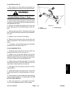
WARNING
Before jacking up the machine, review and follow
Jacking Instructions in Chapter 1 -- Safety.
5. Jack up both sides of the frame enough to lower
swing arm and engine tray assembly.
A. Chock the front and rear of both front tires to pre-
vent the vehicle from moving.
B. After raising the machine, support both sides of
the frame with appropriate jack stands positioned
just in front of the r ear axle tubes. This will allow the
swing arm and engine tray assembly to be lowered
from the vehicle.
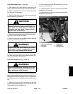
CAUTION
When lowering swing arm and engine tray as-
sembly, make sure hoist can support the total
weight of the engine, transaxle, engine tray and
other attached components. Total weight is
approximately 325 pounds (148 kg).
6. Attach hoist to the engine tray toallow swingarm, en-
gine and transaxle to be lowered from the vehicle. Make
sure hoist is attached to hold the full weight of the swing
arm, engine, transaxle and tray.
7. Remove cap screw and lock nut that secure both
shock absorbers to swing arm.
8. Remove cap screws, thrust washers and lock nuts
that secure swing arm to machine frame.
IMPORTANT: Take care to not damage the engine,
transaxle, fuel hoses, electrical harness or other
parts while lowering the swing arm and engine tray
assembly.
9. Carefully,lower swing arm andengine tray assembly
just enough to allow clearance for swing arm removal.
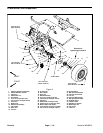
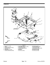
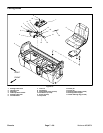
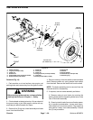
1. Engine
2. Washer (4 used)
3. Cap screw (4 used)
4. Swing arm
5. Engine tray
6. Flange nut (2 used)
7. Mount (2 used)
8. Transaxle
9. Cap screw (2 used)
10. Washer (2 used)
Figure 14
6
7
5
10
3
4
2
1
8
9
4
FRONT
RIGHT
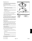
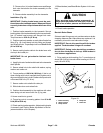
1. Cap screw
2. Flat washer
3. Swing arm bracket
4. Isolation mount
5. Engine tray
6. Flange nut
Figure 15
1
2
4
3
5
6
10.Support swing arm and engine tray assembly in this
slightly lowered position to prevent it from shifting or fal-
ling.
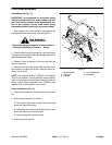
11.Remove both flange nuts, flat washers and cap
screws that secure the engine tray to thes wing arm (Fig.
14).
12.Remove four (4) capscrews and flat washers thatse-
cure the transaxle to the swing arm (Fig. 14).
13.Remove swing arm from assembly.
Chassis