


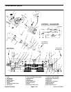

Workman MD/MDXPage 6 -- 16Electrical System
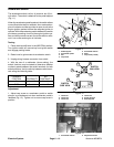
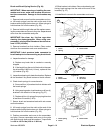
Oil Pressure Switch (Workman MDX)
The oil pressure switch is located on the mounting
adapter for the oil filter.It is a normally closed switch that
opens with pressure.
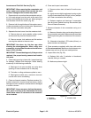
Oil pressure switch testing
1. Turn the ignition switch to ON. The oil indicator light
on the dash should be illuminated.
2. If the light is not on, disconnect the wire from the oil
pressure switch and ground the wire to the engine block.
3. If the light comes on, the oil pressure switch is faulty.
4. If the light does not come on after step 2, check the
indicating circuit (see Electrical Schematic in Chapter 8
-- Electrical Diagrams).
If the oil indicator light comes on with the engine
running:
1. Shut off the engine immediately.
2. Disconnect the wire from the oil pressure switch.
3. Turn the ignition switch to ON. The oil indicator light
should go out.
4. If the light is still on, check for short circuiting in the
indicating circuit (see Electrical Schematic in Chapter 8
-- Electrical Diagrams).
5. Refer to the Briggs and Stratton Repair Manual for 4
Cycle, V--Twin Cylinder, OHV Head Engines for addi-
tional testing information.
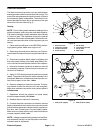
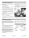
Figure 19
1. Oil pressure switch
2. Generator belt
1
2
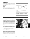
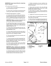
Audio Alarm (Reverse) (Optional)
If vehicle is equipped with the optional audio alarm,
whenever the shift lever is placed in the reverse position
the audio alarm should sound. The alarm is attached be-
neath the cargo box to a bracket on the right side of the
frame.
Testing
1. Place machine shift lever in the NEUTRAL position.
Make sure that ignition switch is off, remove key from
ignition switch and engage parking brake.
2. Raise cargo box and secure with prop rod. Gain ac-
cess to audio alarm by removing the electrical c over.
IMPORTANT: Make sure to observe polarity on the
alarm terminals when testing. Damage to the alarm
may result from an improper connection.
3. Disconnect wire harness connector from alarm. Cor-
rectly connect 12VDC source to the terminals (Fig. 20).
Alarm should sound.
4. Remove voltage source from the alarm. Replace
alarm if necessary. Connect wire harness connector to
alarm.
5. Install electrical cover and lower cargo box.
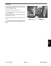
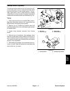
1. Top view
2. Bottom view
3. Positive (+) terminal
4. Negative (--) terminal
Figure 20
3
2
4
1