


Workman MD/MDX Drive TrainPage 5 -- 17
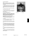
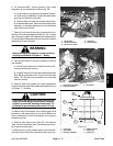
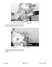
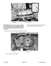
6. On Workman MD, remove governor and cable
brackets from the transaxle as follows (Fig. 23).
A. Scribe mark across governor bracket and gover-
nor shaft to help installation. Loosen both set screws
securing the bracket to the shaft.
B. Remove both lock nuts securing the cable brack-
et to the transaxle case. Remove both brackets and
cables as a complete assembly from the transaxle
case and governor shaft.
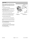
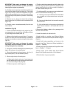
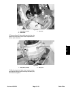
7. Remove lock nut that secures the select lever as-
sembly to the transaxle selector shaft (Fig. 24). Loosen
jam nuts securing both shift cables to the c able bracket
on the transaxle. Separate select lever and shift cables
assembly from the transaxle.
WARNING
Before jacking up the machine, review and follow
Jacking Instructions in Chapter 1 -- Safety.
8. Jack up both sides of the frame enough to remove
rear wheels.
A. Chock the front and rear of both front tires to pre-
vent the vehicle from moving.
B. Support both sides of the frame with appropriate
jack stands positioned just in front of the rear axle
tubes. This will allow the transaxle to be removed
from the vehicle.
9. Remove both rear wheels and brake assemblies
from the transaxle (see Rear Wheel and Brake Removal
in Chapter 7 -- Chassis).
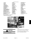
CAUTION
When removing engine tray, make sure hoist can
support the total weight of the engine, transaxle,
engine tray and other attached components. To-
tal weight is approximately 300 pounds (137 kg).
10.Attach hoist to the engine tray to allow engine and
transaxle to be lowered from the vehicle. Make sure
hoist is attached to hold the full weight of the engine,
transaxle and tray.
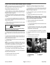
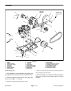
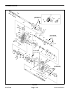
11.Remove both flange nuts ( item 20), flat washers
(item 18) and cap screws (item 19) that secure the en-
gine tray to the swing arm.
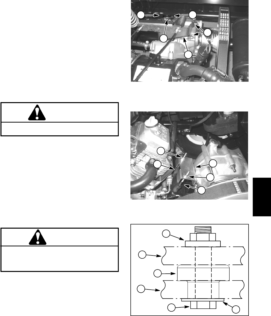
12.Remove four (4) cap screws (item 3) and flat wash-
ers (item 2) that secure the transaxle to the swing arm.
1. Scribe mark
2. Governor bracket
3. Set screw (2 used)
4. Lock nuts
5. Cable bracket
Figure 23
1
2
5
3
4
1. Select lever assembly
2. Lock nut location
3. Shift cable
Figure 24
1
3
2
3
2
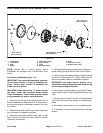
1. Cap screw
2. Flat washer
3. Swing arm bracket
4. Isolation mount
5. Engine tray
6. Flange nut
Figure 25
1
2
4
3
5
6
Drive Train