


Rev. A
Workman MD/MDX Drive TrainPage 5 -- 13
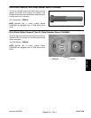
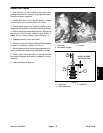
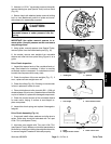
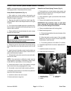
3. Use two 1/4--20 X 1” cap screws to secure the spider
removal holding bar (see Special Tools) to drive clutch
(Fig. 16).
4. Secure clutch with attached spider removal holding
bar in a vise. Matchmark position of spider and move-
able sheave for reassembly purposes.
CAUTION
Remove spider from fixed sheave slowly. The
moveable sheave is under pressure from the
spring.
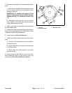
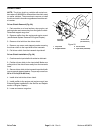
IMPORTANT: Use spider removal spanner to re-
move spider. Unequal pressure on the cam towers
may damage them.
5. Using spider removal spanner (see Special Tools),
remove spider from the fixed sheave post (Fig. 16).
6. As needed, remove cam weights from moveable
sheave and roller kits from spider using Figure 14 as a
guide.
Drive Clutch Inspection
1. Inspect the tapered ends of the crankshaft and pri-
mary fixed sheave for scratches. If either is severely
scratched, replace component. If scratches are minor,
burnish the component with emery cloth.
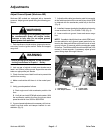
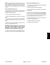
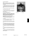
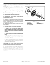
2. Check the surface of the cam weights (Fig. 17). If
worn, replace all cam weights as a set.
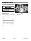
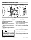
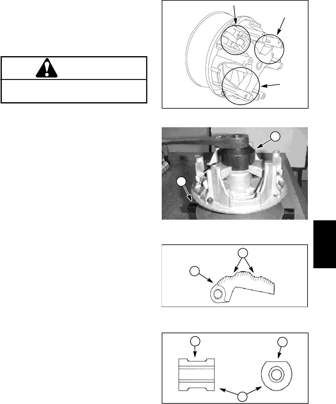
3. Check the rollers (Fig. 18). If binding or uneven wear
is found, replace all rollers as a set.
4. Clean pilot bolts and roller pins w ith 800 -- 1000 grit
abrasive paper.If the chrome--plated surface of the bolts
or pins is scaled off, replace the damaged components.
5. Check the contact surface of the moveable sheave
for wear and/or fraying. If surface is worn/frayed, re-
place component.
6. Inspect the clutch spring and replace if damaged or
fatigued.
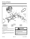
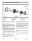
Drive Clutch Assembly (Fig. 14)
1. If removed, install rollers, washers and roller pins to
spider. Roller pins should be lubricated with Toro part
#104--7011 (see Special Tools).
2. Lubricate cam weights with Toro part #104--7011
(see Special Tools). Make sure lubricant penetrates to
pilot bolts by rotating and sliding the weights side to side,
or remove weights if needed to lubricate properly.
Figure 15
1. Holding bar 2. Spanner
Figure 16
1
2
1. Cam weight 2. Worn contact surface
Figure 17
1
2
1. Roller
2. Weight contact surface
3. Roller uneven wear
Figure 18
2
3
1
Drive Train