


Workman MD/MDXPage 7 -- 28Chassis
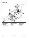
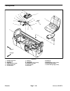
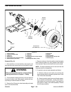
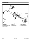
Rear Wheels and Brakes
1. Wheel assembly
2. Lug nut (5 used per hub)
3. Castle nut
4. Brake drum
5. Socket head screw (4 used per brake)
6. Brake assembly (LH shown)
7. Clevis pin
8. Cotter pin
9. Cotter pin
10. Flange lock nut (4 used per brake)
11. Transaxle
12. Parking brake cable (2 used)
13. Wheel hub
14. Washer
15. Spring washer
16. Wheel stud (5 used per hub)
17. Retaining ring
Figure 18
FRONT
RIGHT
10
9
8
7
6
5
4
1
2
11
12
3
45 to 65 ft--lb
(61to88N--m)
120 ft--lb
(163 N--m)
13
14
15
20 ft--lb
(27 N--m)
Antiseize
Lubricant
16
17
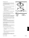
Removal (Fig. 18)
1. Park machine on a level surface, stop engine, set
parking brake and remove key from the ignition switch.
WARNING
Before jacking up the machine, review and follow
Jacking Instructions in Chapter 1 -- Safety.
2. Chock wheels not being jacked up. Lift rear wheel off
the ground using a jack and support vehicle with ap-
propriate jack stand beneath the frame.
3. Remove five (5) lug nuts, wheel assembly and brake
drum from the wheel hub.
4. Remove cotter pin from the castle nut and transaxle
shaft. Remove castle nut, spring washer and washer
from the shaft. Remove the wheel hub from the shaft.
NOTE: The brake assembly can be removed from the
transaxle shaft for disassembly.
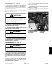
5. If required, remove brake assembly as follows:
A. Remove cotter pin and clevis pin securing the
parking brake cable to the parking brake lever on the
rear of the brake assembly.
B. Clean hydraulic brake line area of brake assem-
bly to prevent contamination. Loosen and discon-
nect brake line from wheel cylinder. Plug brake line
and position it away from brake assembly. Discard
two (2) banjo washers.