


Workman MD/MDX Page 7 -- 21 Chassis
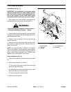
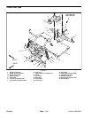
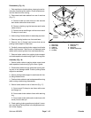
Pivot Yoke Removal (Fig. 11 and 12)
1. Park machine on a level surface, stop engine, set
parking brake and remove key from the ignition switch.
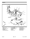
2. Remove cargo box from the rear frame (see Cargo
Box Removal in this section).
3. Remove seat base from the front frame (see Seat
Base Removal in this section).
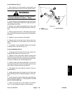
WARNING
Make sure all tires are chocked to prevent the
machine from moving. Beforeremoving the pivot
yoke, make sure front and rear frames are
supported with jack stands. Support both the
front and back of each frame.
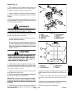
4. Remove four (4) cap screws and flat washers secur-
ing the pivot yoke to the rear frame.
5. Remove cap screw and hardened washer securing
the pivot yoke to the front frame tab.
WARNING
Support pivot yoke while removing it from the
front frame to prevent dropping and causing
serious injury and damage to the machine.
6. Remove four (4) flange head screws and flanged
lock nuts securing the pivot yoke to the front frame. Re-
move pivot yoke from the machine.
Pivot Yoke Installation (Fig. 11 and 12)
WARNING
Support pivot yoke while installing it to the front
frame to prevent dropping and causing serious
injury and damage to the machine.
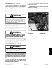
1. Position pivot y oke to the front frame so the diamond
pattern faces up. Secure yoke to front frame with four (4)
flange head screws and flanged lock nuts. Tighten lower
two (2) fasteners first, then tighten upper two (2) fasten-
ers.
2. Secure pivot yoke to the front frame tab with cap
screw and hardened washer. Torque cap screw from
240 to 290 ft--lb (326 to 393 N--m).
3. Secure pivot yoke to the rear frame with four (4) cap
screws and flat washers.
4. Install seat base to the front frame (see Seat Base
Installation in this section).
5. Install cargo box to the rear frame (see Cargo Box
Installation in this section).
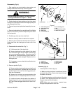
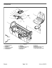
1. Cap screw & flat washer
2. Pivot yoke
3. Rear frame
4. Flange lock nut
5. Front frame
6. Diamond pattern
Figure 12
3
2
1
6
5
4
Chassis