


Rev. A15.1
Workman MD/MDXDrive Train Page 5 --
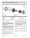
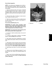
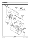
Driven Clutch Service (Serial Number Above 310000000)
NOTE: Vehicles with a serial number above
310000000 are equipped with a TEAM brand driven
clutch (Fig. 21.1).
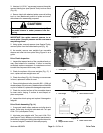
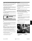
1. Use a suitable press to compress the clutch spring
enough to allow removal of the retaining ring (item 7).
2. Remove retaining ring.
3. Carefully, allow the spring to extend fully.
4. Remove outer spring retainer, spring and inner
spring retainer from clutch.
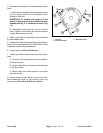
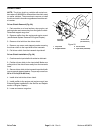
5. Make note of the “X” mark cast into the fixed sheave
and moveable sheave before removing the moveable
sheave. These marks must be aligned during assembly
for proper clutch operation.
6. Separate the clutch sheaves. Locate and retrieve
thrust washer.
7. Clean and inspect driven clutch components:
A. Clean all dust and debris from clutch compo-
nents. If necessary, use contact or brake cleaner to
remove any oil or other lubricants from c lutch com-
ponents.
B. Inspect the spring and replace if damaged or fa-
tigued.
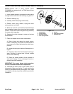
C. Check therollers in the fixed sheavefor binding or
wear. If binding or uneven wear is found, replace
driven clutch assembly.
D. Check the contact surface of the sheaves for
wear and/or fraying. If wear or damage is found, re-
placedrivenclutchassembly.
IMPORTANT: For proper driven clutch operation,
DO NOT lubricate driven clutch components.
8. Assemble the driven clutch in the reverse order of
disassembly. Make sure that the “X” mark cast into the
fixed and moveable sheaves are aligned. Also, make
sure that the retaining ring is fully seated in groove after
installation.
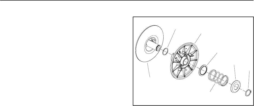
1. Fixed sheave
2. Thrust washer
3. Moveable sheave
4. Inner spring retainer
5. Spring
6. Outer spring retainer
7. Retaining ring
Figure 21.1
2
3
6
1
5
7
4