


Rev. A
Workman MD/MDX Drive TrainPage 5 -- 15
Driven Clutch Service (Serial Number Below 310000000)
NOTE: Vehicles with a serial number below 310000000
are equipped with a Comet brand driven clutch.
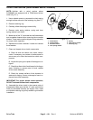
Ramp Button Replacement (Fig. 21)
1. Park vehicle on a level surface, stop engine, set
parking brake and remove key from the ignition switch.
Raise and support cargo box.
2. Remove drive belt from the driven clutch (see Ser-
vice Drive Belt in Service and Repairs section of Engine
Chapter).
3. Turn fixed and moveable sheaves in opposite direc-
tions so button is separated sufficiently enough from the
ramp to allow removal.
4. Place small block of wood between the outer ramps
to keep the ramps apart.
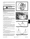
CAUTION
To prevent burns, hold a llen wrench with locking
pliers when heating allen wrench.
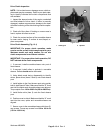
5. Clamp long end of a 2 mm allen wrench with locking
pliers. Heat short end of the allen wrench until it is red
hot.
6. Insert hot end of the allen wrench into the button so
it melts around the end of the wrench. Hold wrench in
place until the button hardens.
7. Pull and twist on the allen wrench to remove the but-
ton from the ramp.
NOTE: If the new button is difficult to install, sand its
mounting tab as necessary. If the button is loose, apply
Loctite #242 (or equivalent) on its mounting tab.
8. Install new button to ramp. Push button in straight
with a screw driver by prying against the ramp.
9. As needed, remove and install remaining buttons.
10.Carefully remove block of wood that was placed to
keep the clutch ramps apart.
11.Install drive belt to the driven clutch.
12.Lower and secure cargo box.
Check Driven Clutch Spring Tension (Fig. 21)
1. Park machine on a level surface, stop engine, set
parking brake and remove key from the ignition switch.
Raise and support cargo box.
2. Place transaxle in gear to prevent the fixed sheave
from moving.
3. Remove drive belt from the driven clutch.
IMPORTANT: U se protective strips of soft metal
when clamping the moveable sheave with locking
pliers to prevent damage to the sheave.
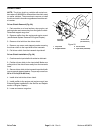
4. Clamp moveable sheave with locking pliers.
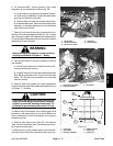
5. Measure spring torsion.
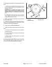
A. Pull scale tangentially to the outer diameter of the
moveable sheave.
B. When the button on the ramp of the moveable
sheave is 0.125 inch (3.18 mm) from the ramp of the
fixed sheave, read the scale.
C. The reading should be 16 to 20 lbf (71 to 89 N).
6. If the above specification is not met, replace the driv-
en clutch.
7. Install drive belt to driven clutch.
8. Lower and secure cargo box.
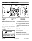
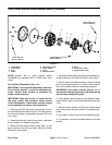
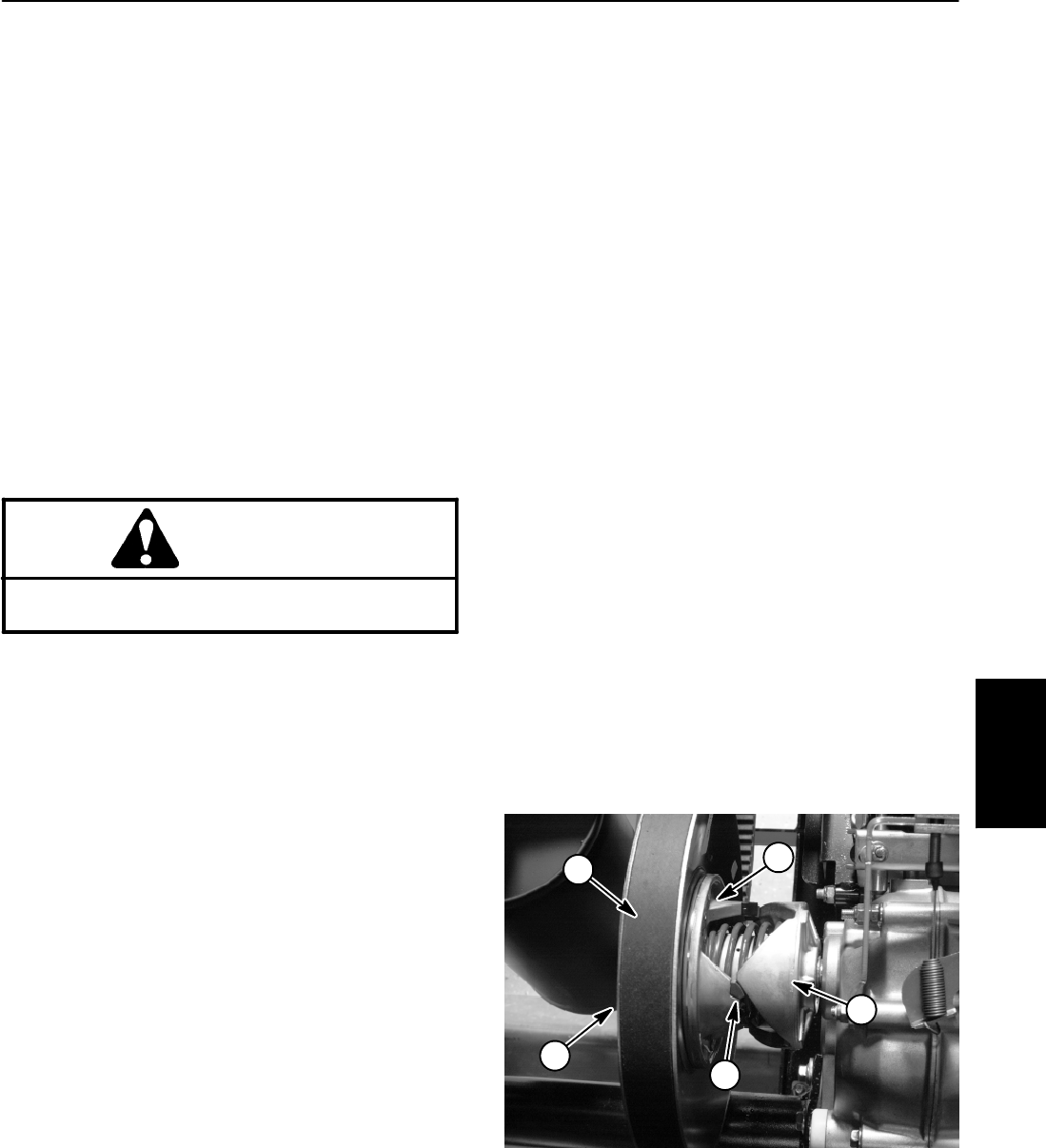
1. Moveable sheave
2. Ramp (fixed cam)
3. Button
4. Fixed sheave
5. Drive belt
Figure 21
3
2
1
5
4
Drive Train