


Workman MD/MDX Page 7 -- 29 Chassis
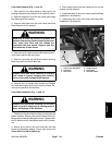
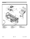
C. Remove four (4) socket head screws and flange
lock nuts that secure the brake assembly to the
transaxle.
D. Remove brake assembly from the transaxle.
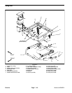
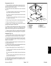
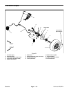
Installation (Fig. 18)
IMPORTANT: Parking brake levers must be posi-
tioned above the transaxle mount. When positioned
correctly,brake lever will point towardthe rear of the
axle.
1. Position brake assembly to the transaxle. Secure
backing plateof the brake assembly tothe transaxle with
four (4) socket head screws and flanged lock nuts.
Torque screws to 20 ft--lb (27 N--m).
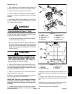
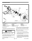
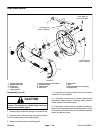
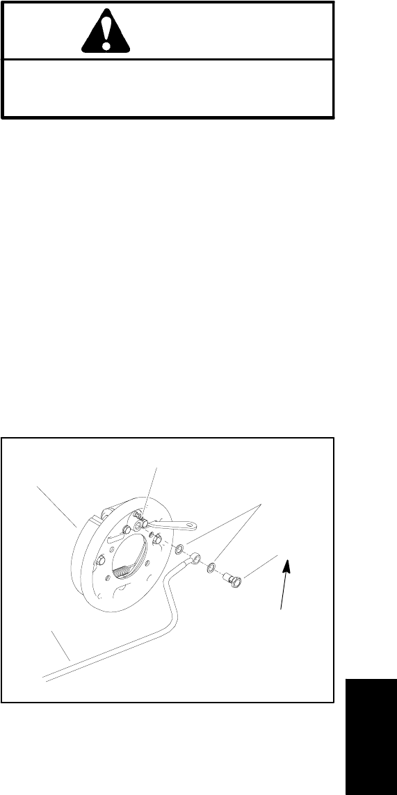
2. Position new banjo washer on each side of brake line
fitting (Fig. 19). Insert banjo bolt into fitting and thread
into wheel cylinder. Torque banjo bolt from 15 to 21 ft--lb
(21to28N--m).
3. Secure parking brake cable to the brake lever with
clevis pin and cotter pin.
IMPORTANT: Do not get antiseize lubricant onto
brake shoes.
4. Apply light coat of antiseize lubricant to the transaxle
shaft splines.
5. Secure wheel hub to the shaft with washer, spring
washer and castle nut.
6. Torque castle nut 120 ft--lb (163 N--m).Ifslotinnut
does not align with hole in transaxle shaft, tighten nut to
align next slot with holein shaft. Castle nut torque should
not exceed 200 ft--lb (271 N--m).
7. Secure castle nut to shaft with cotter pin.
8. Slide brake drum onto wheel hub.
9. Position wheel assembly to the machine with valve
stem facing out and secure with five (5) lug nuts.
10.Lower machine to ground.
11.Torque lug nuts in a crossing pattern from 45 to 65
ft--lb (62 to 88 N --m).
12.Check parking brake operation.Adjust parking brake
if necessary (see Parking Brake Adjustment in the Ad-
justments section of this chapter).
13.Bleed brakes (see Bleed Brake System in this sec-
tion).
CAUTION
After servicing brake system components, al-
ways check the brakes in a wide open, level area
that is free of other persons and obstructions.
14.Check brake operation.
Burnish Brake Shoes
Sintered metal linings may not provide maximum brake
stopping distance after brake shoes are replaced. It is
necessary to burnish new brake shoe linings.
IMPORTANT: Do not drive machine with the brakes
applied. The brake shoe linings will overheat.
IMPORTANT: During brake burnishing procedure,
do not allow the brakes to lock up. Allow brakes to
cool between applications.
1. Drive machine while making 6 to 7 normal stops at
about 200 ft (60 m) intervals while traveling at 10 to 15
mph (16 to 24 KPH).
1. Brake assembly
2. Wheel cylinder
3. Banjo washer
4. Banjo bolt
5. Brake line
Figure 19
5
4
1
2
3
15 to 21 ft--lb
(21to28N--m)
Chassis