


Workman MD/MDX Page 7 -- 15 Chassis
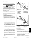
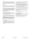
Disassembly (Fig. 6)
1. Park machine on a level surface, stop engine, set
parking brake and remove key from the ignition.
WARNING
Before jacking up the machine, review and follow
Jacking Instructions in Chapter 1 -- Safety.
2. Chock wheels not being jacked up. Jack front wheel
off the ground and support vehicle with appropriate jack
stand beneath the frame.
3. Remove lug nuts and pull wheel assembly from ma-
chine.
4. Remove brake caliper from spindle (see Front Brake
Caliper in this section). Positioncaliper away from wheel
hub and spindle.
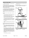
5. Carefully pry dust cap from wheel hub.
6. Remove cotter pin and nut retainer from spindle.
7. Remove jam nut that secures wheel hub to spindle.
Slide wheel hub with bearings and brake rotor from
spindle.
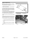
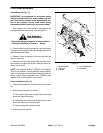
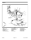
8. Disassemble the wheel hub (Fig. 7):
A. Pull the seal out of the wheel hub.
B. Remove bearings from both sides of the wheel
hub. Clean bearings in solvent. Make sure bearings
are in good operating condition. Clean the inside of
the wheel hub. Check the bearing cups for wear, pit-
ting or other noticeable damage. Replace worn or
damaged parts.
C. If necessary,remove wheel studs and brake rotor
from wheel hub.
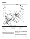
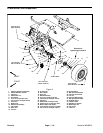
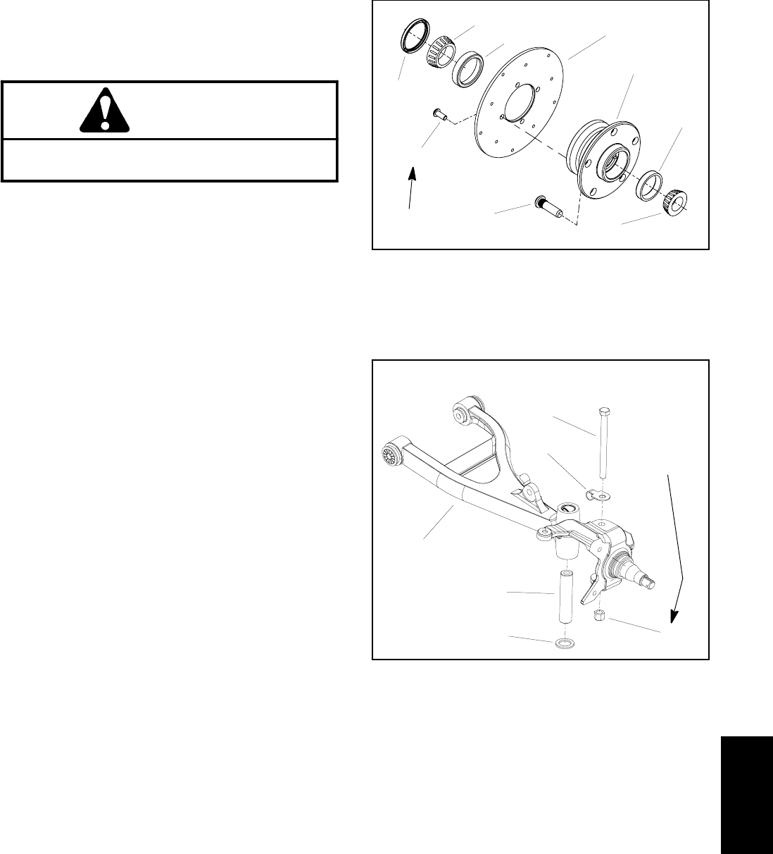
9. Remove spindle (Fig. 8):
A. Remove cotter pin and castle nut securing tie rod
ball joint to the spindle. Separate ball joint from the
spindle. Remove tie rod from steering gearbox pit-
man arm if necessary.
B. Remove lock nut and cap screw securing the
spindle to the A--arm. Separate spindle from A --arm.
C. Locate and remove thrust washer from bottom of
kingpin sleeve in A--arm and brake hose clip from top
of A--arm. Remove kingpin sleeve from A--arm if nec-
essary.
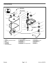
1. Outer bearing cone
2. Outer bearing cup
3. Wheel hub
4. Brake rotor
5. Inner bearing cup
6. Inner bearing cone
7. Seal
8. Socket screw (4 used)
9. Wheel stud (5 used)
Figure 7
1
2
3
4
5
6
7
8
9
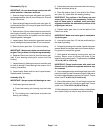
Loctite #242
1. Cap screw
2. Brake hose clip
3. A--arm (LH shown)
4. Kingpin sleeve
5. Thrust washer
6. Lock nut
Figure 8
1
2
3
4
56
75 to 100 ft--lb
(102 to 135 N--m)
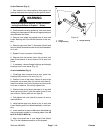
Assembly (Fig. 6)
1. Install spindle as follows (Fig. 8):
A. Make sure king pin sleeve is positioned into the
pivot hub of the A--arm. Sleeve must extend through
the bottom of the hub.
B. Place thrust washer onto the bottom of the king
pin sleeve. Then place spindle over the A--arm hub,
king pin sleeve and thrust washer.
NOTE: Make sure cap screw is inserted down
through the spindle and A--arm hub.
Chassis