


Workman MD/MDX Page 6 -- 9 Electrical System
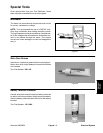
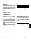
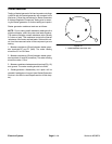
Hour Meter
Testing
IMPORTANT: Make sure to observe polarity on the
hour meter terminals when testing. Damage to the
meter may result from an improper connection.
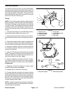
1. Unplug wire harness connector from hour meter.
2. Connect positive (+) terminal of a 12 VDC source to
the positive terminal of the hour meter.
3. Connect negative (--) terminal of the voltage source
to the other terminal of the hour meter.
4. The hour meter should move 1/10 of an hour in six
(6) minutes.
5. Disconnect voltage source from the hour meter. Re-
connect wire harness connector to hour meter.
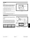
Figure 6
RUNNING: INDICATOR
WINDOW
1/10 WHEEL: WHITE W/BLACK NUMBERS
HOUR WHEELS: BLACK W/WHITE NUMBERS
1
--
10
HOURS
00000
QUARTZ
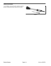
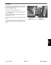
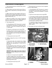
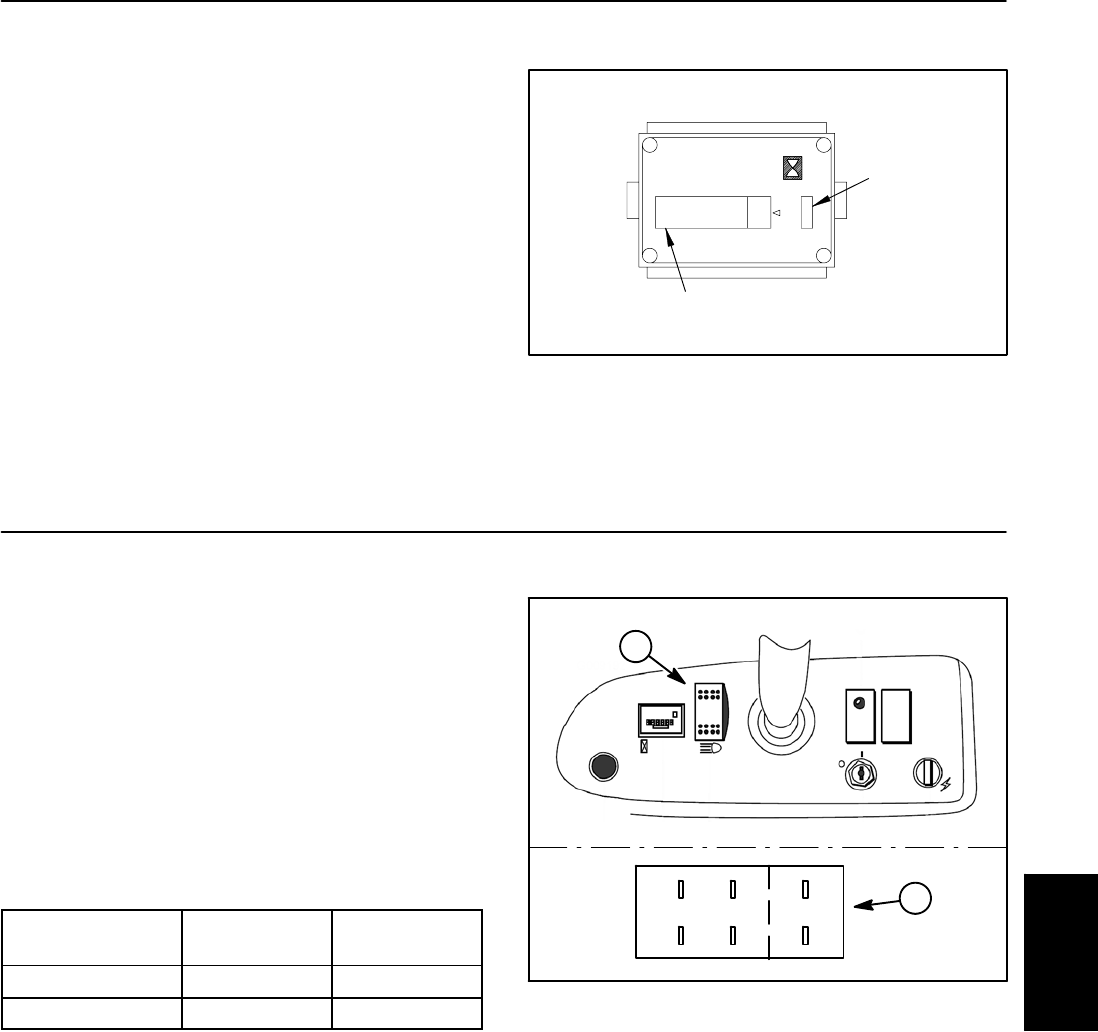
Headlight Switch
The headlight switch is located on the control panel (Fig.
7). This rocker switch allows the headlights to be turned
on and off.
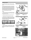
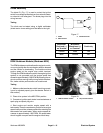
Testing
The switch terminals are marked as shown in Figure 7.
The circuitry of the headlight switch is shown in the chart
below. With the use of a multimeter (ohms setting), the
switch functions may be tested to determine whether
continuity exists between the various terminals for each
position. Verify continuity between switch terminals.
SWITCH
POSITION
NORMAL
CIRCUITS
OTHER
CIRCUITS
ON 2+3 5+6
OFF 1+2 4+5
1. Headlight switch 2. Back of switch
Figure 7
132
45 6
1
2
Electrical
System