


Workman MD/MDX Page 7 -- 19 Chassis
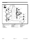
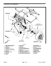
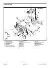
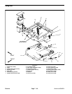
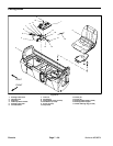
A--arm Removal (Fig. 9)
1. Park machine on a level surface, stop engine, set
parking brake and remove key from the ignition switch.
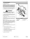
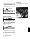
WARNING
Before jacking up the machine, review and follow
Jacking Instructions in Chapter 1 -- Safety.
2. Chock wheels not being jacked up. Jack front wheel
off the ground and support vehicle with appropriate jack
stand beneath the frame.
3. Remove front wheel and spindle from A--arm ( see
Lower Steering and Front Wheel Removal in this sec-
tion).
4. Remove cap screw (item 7), flat washer (item 5) and
lock nut (item 6)that secure lower end of shock absorber
to A--arm.
5. Support A--arm to prevent it from falling.
6. Remove both cap screws (item 19) and lock nuts
(item 6) that secure A --arm to frame. Pull A--arm from
frame.
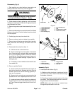
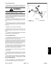
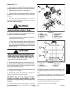
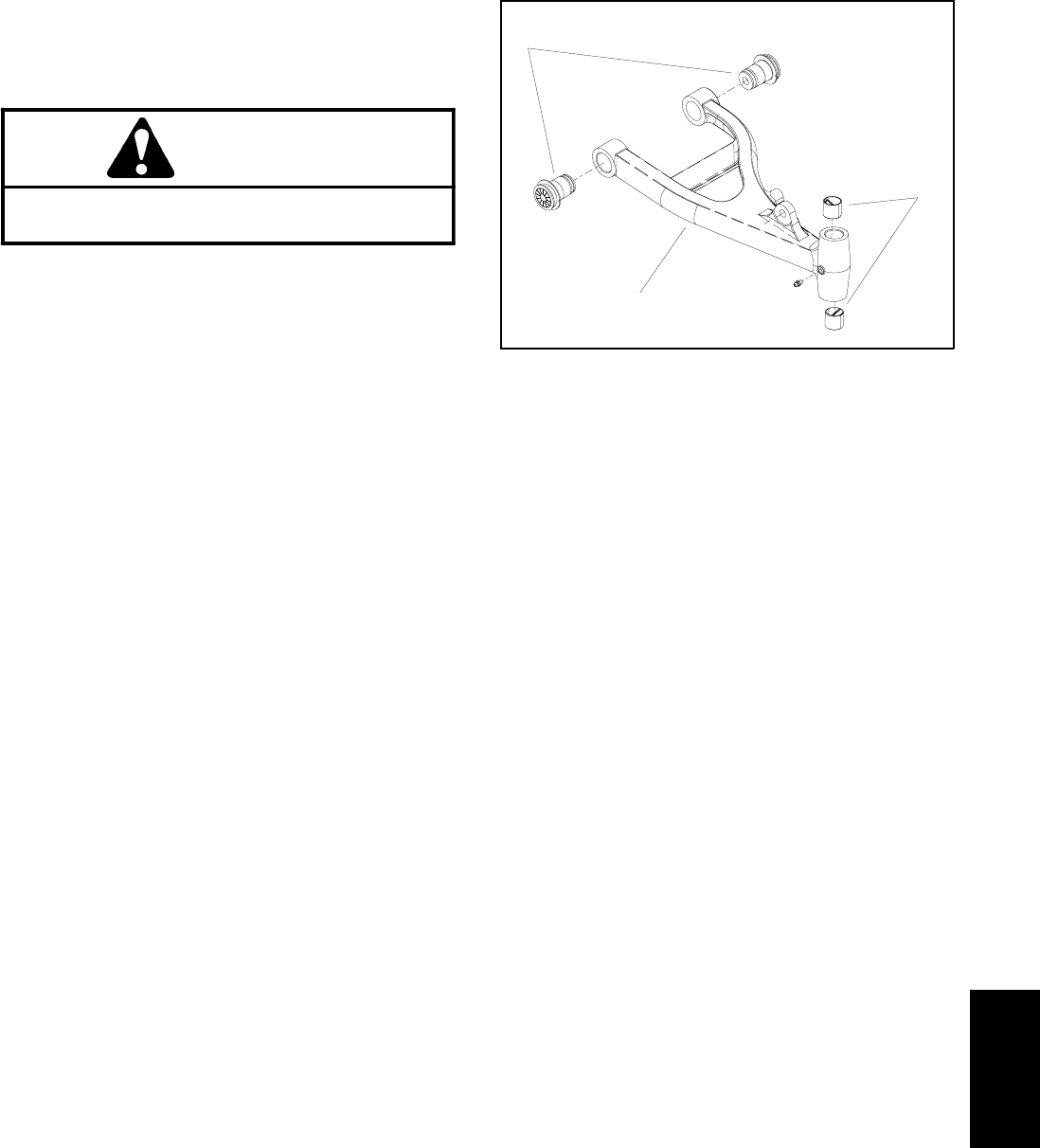
7. If necessary, remove flange bushings and straight
bushings from A--arm bores (Fig. 10).
A--arm Installation (Fig. 9)
1. If bushings were removed from A--arm, press new
bushings fully into bore of A--arm (Fig. 10).
2. Position A--arm to the frame. Secure A--arm to the
frame with cap screws (item 19) and lock nuts (item 6).
Insert front screw from front of machine and rear screw
from rear of machine. Do not fully tighten nuts.
3. Position lower end of shock absorber to A--arm and
insert cap screw (item 7) with flat washer (item 5) from
rear of shock. Secure with lock nut (item 6).
4. Fully tighten lock nuts (item 6) to secure A--arm to
machine frame.
5. Install spindle and front wheel to the A--arm (see
Lower Steering and Front Wheel Installation in this sec-
tion).
6. Lower machine to ground. Make sure that wheel lug
nuts are properly torqued in a crossing pattern from 45
to 65 ft--lb (62 to 88 N--m).
7. Align front wheel toe--in (see Adjust Front Wheel
Toe--in in the Adjustments section of this chapter).
1. A--arm
2. Flange bushing
3. Straight bushing
Figure 10
2
3
1
Chassis