


Workman MD/MDXPage 6 -- 8Electrical System
Component Testing
For accurate resistance and/or continuity checks, elec-
trically disconnect the component being tested from the
circuit (e.g. unplug the ignition switch connector before
doing a continuity check on the switch).
NOTE: See the Briggs and Stratton Repair Manual for
4 Cycle, V--Twin Cylinder, OHV Head Engines (Work-
man MDX) or the Kohler Service Manual for Command
Pro CS Series Engines (Workman MD) for additional
component testing information.
CAUTION
When testing electrical components for continu-
ity with a multimeter (ohms setting), make sure
that power to the circuit has been disconnected.
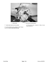
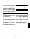
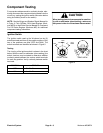
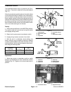
Ignition Switch
The ignition switch used on the Workman has six (6)
switch terminals and three (3) key switch positions. Only
two of the positions are used (OFF and RUN). The
switch terminals are identified as shown in Figure 5.
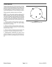
Testing
The circuitry of the ignition switch is shown in the chart
below. With the use of a multimeter (ohms setting), the
switch functions may be tested to determine whether
continuity exists between the various switch terminals
for each key position. Verify continuity between switch
terminals.
POSITION
CIRCUIT
OFF D+E+F
ON A+C+F
Figure 5
REAR VIEW
FRONT VIEW
A
B
C
D
E
F
NOT
OFF
RUN
45
o
45
o
USED