


Workman MD/MDX Page 6 -- 25 Electrical System
Battery Service
The battery is the heart of the electrical system. With
regular and proper service, battery life can be extended.
Additionally, battery and electrical component failure
can be prevented.
WARNING
POTENTIAL HAZARD:
Either the battery terminals or metal tools could
short against metal vehicle components.
WHAT CAN HAPPEN:
Sparks can cause the battery gasses to explode.
Damaged cables could short against metal ve-
hicle components and cause sparks.
HOW TO AVOID THE HAZARD:
When removing or installing the battery, do not
allow the battery terminals to touch any metal
parts of the vehicle.
Always DISCONNECT the negative (black) bat-
tery cable before disconnecting the positive
(red) cable.
Always CONNECT the positive (red) battery
cable before connecting the negative (black)
cable.
Do not allow metal tools to short between the
battery terminals and metal parts of the ve-
hicle.
Always keep the battery retaining components
secure to protect the battery.
Battery Specifications
BCI Group Size U1
300 Amp Cranking Performance at 0
o
F (--17.8
o
C)
Reserve Capacity at 25 Amps and 80
o
F (26.7
o
C)
is 28 Minutes
Electrolyte Specific Gravity
Fully charged: 1.265 corrected to 80
o
F (26.7
o
C)
Discharged: less than 1.240
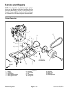
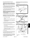
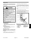
Battery Removal (Fig. 30)
IMPORTANT: B e careful to not damage terminal
posts or cable connectors when removing the bat-
tery cables.
1. Position vehicle on a level surface, set parking
brake, turn ignition switch off and remove key.
2. Raise cargo box and secure with prop rod.
3. Disconnect negative (black) cable from battery first
to prevent short circuiting the battery, other components
or operator’s hands. Then disconnect positive (red)
cable.
4. Remove wing nuts and hold down rod that secure
battery.
5. Make sure that filler c aps are on tightly.
6. Remove battery from chassis to a service area. This
will minimize possible battery damage and allow better
access for battery inspection and service.
1. Wing nut (2 used)
2. Hold down rod
3. Positive cable (red)
4. Battery
5. Post (2 used)
6. Battery base
7. Battery tray
8. Negative cable (black)
9. Flange screw (2 used)
10. Flange nut (2 used)
11. Battery cover
Figure 30
4
5
3
2
1
6
7
8
9
10
11
Electrical
System