


4-56 Chapter 4: Built-In Images
Model 801GC, 801GF & 801GX¥Rev. X1
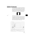
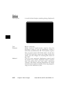
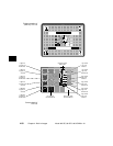
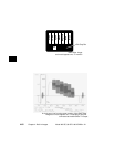
following illustration. The patches are located
in each corner of the main image and in the
center. They’re oriented with the highest
resolution and contrast boxes closest to the
outside corners. The 48%-53%, 48%-51% and
50%-51% level patches are omitted in the
secondary version.
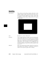
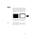
4) Gray-Scale Boxes – Twelve (12) boxes at
eleven (11) intensity levels are clustered
around the center of the main image. They
start at 0% and increase in 10% steps to 100%
with two (2) boxes at a 50% level. All of the
gray-scale boxes are omitted in the secondary
version.
5) Gamma Check Dither Box – A small box is
drawn inside the right-hand 50% gray-scale
box. The box is half the width and height of
the larger box. The box consists of a checker-
board of alternate one-on and one-off pixels.
The alternate pixels have levels of 0 and 100%.
This smaller box is not part of the original
SMPTE specification and is omitted in the
secondary version.
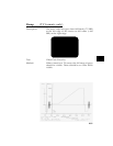
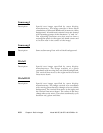
6) Contrast Boxes – Two (2) boxes are drawn
adjacent to the gray-scale boxes. They’re at
0 and 100% levels. There are smaller boxes
drawn inside each box at 5 and 95% levels.
The contrast boxes are omitted in the
secondary version.
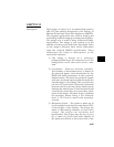
7) Black & White Windows – Two (2) horizontal
bars are located above and below the gray-
scale boxes. Their height equals 8% of the
display height. There are half-size bars
centered in the larger bars. In the primary
version, the dark portion of the windows is
at a 5% level and the bright portion is at a
95% level. Zero and 100% levels are used in
the secondary version.