


4-42 Chapter 4: Built-In Images
Model 801GC, 801GF & 801GX¥Rev. X1
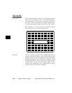
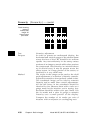
Outline0 and Outline1 — contd.
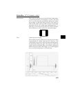
Test Yoke tilt correction
Purpose The horizontal axis of a displayed image should line
up with the horizontal axis of your monitor. Any
tilt is likely due to the yoke being rotated on the
neck of the CRT. A rotated yoke makes any displayed
image appear rotated.
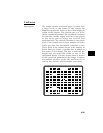
Method Place your monitor on a flat surface so the face of
the CRT is perpendicular to the surface. Use a
ruler or gauge to measure the height of each end
of the image’s horizontal center line from the
surface. The difference between the two readings
should be within spec for the monitor. If it’s out
of spec, the yoke needs to be adjusted. Loosen
the hardware that clamps the yoke to the neck of
the CRT and rotate the yoke until the line is
horizontal. Tighten the yoke-clamp hardware.
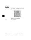
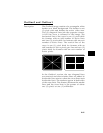
Test Yoke winding orthogonality check
Purpose The horizontal and vertical deflection coils on the
yoke should have their axes cross at exactly 90
degrees. Improper orientation of the windings
causes displayed rectangles to look more like non-
orthogonal parallelograms. This type of defect is
almost impossible to correct with adjustments. It’s
usually easier to replace the defective yoke.
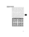
Method First perform the previously discussed yoke tilt test.
The vertical center line of the image should be
perpendicular to the work surface. If the deviation
is beyond spec, the monitor should be rejected and
sent back for repair before the operator wastes time
trying to magnet a defective yoke.