


4-45
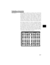
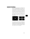
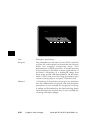
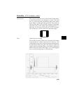
Test Pin and barrel distortion correction
Purpose If perfectly linear sweep signals are sent to a perfectly
wound deflection yoke that’s mounted on a perfect
CRT, you would not necessarily get a perfectly formed
raster. Instead you would likely get a raster that
had its corners stretched away from the center and
resembled a pincushion. This distortion occurs
because the geometry of the deflected electron beam
does not match the geometry of the tube faceplate.
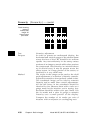
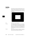
Also, imperfections in the yoke or CRT may affect
this problem. In some cases one or more corners
may be pulled towards the center of the raster causing
it to look like a barrel. Uncorrected raster distortion
carries over as distortion of the displayed image.
Method A slot gauge may be used to determine if the amount
of pincushion or barrel distortion is within limits.
A basic slot gauge may consist of a piece of opaque
film with at least two (2) transparent slots in it.
One slot is used for top and bottom distortion
and the other is used for the sides. By positioning
the correct slot over each portion of the border
line, the entire line should be visible. If this cannot
be done at all four sides, the monitor needs
correcting.
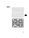
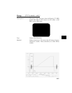
There are two main ways of correcting pincushion
distortion. The first involves placing or adjusting
magnets on the yoke. This is a trial-and-error
method. However, skilled operators develop a feel
for how strong a magnet to use and how to place
it in order to get the desired correction. If any
correction is performed, the Trapezoid Distortion
Correction test should be repeated.
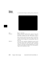
The other correction method involves adding
correction signals to the deflection signal driving
the yoke. This method is usually found in color
monitors, where adding magnets to the yoke would
cause problems with convergence and purity. The
type and number of adjustments depends on the
monitor being tested.