


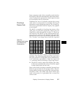

5-11
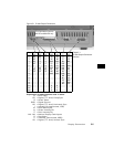
PC / Terminal Wiring
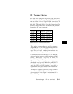
The cable and adapters supplied with the 801G*
should be suitable for most basic RS-232 hook-ups
that use either 9 pin or 25 pin D-Sub connectors. In
some cases, you may need to make your own spe-
cial cable. The table below lists the connections re-
quired to attach the 801G* to the RS-232 port on a
terminal or PC type computer.
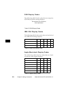
801GX
9 pin D-Sub
Signal
Direction
PC-AT
9-pin D-Sub
PC or Terminal
25-pin D-Sub
pin-1 NC
pin-2 Rx <----- pin-3 Tx pin-2 Tx
pin-3 Tx -----> pin-2 Rx pin-3 Rx
pin-4 DTR -----> pin-6 DSR pin-6 DSR
pin-5 GND ------- pin-5 GND pin-7 GND
pin-6 NC
pin-7 RTS -----> pin-8 CTS pin-5 CTS
pin-8 CTS <----- pin-7 RTS pin-4 RTS
pin-9 NC
Table 5-6PC and Terminal Connections
• This table assumes that you will be connect-
ing the 801G* to an IBM-compatible computer
having either a 9-pin or 25-pin serial connec-
tor. You will note that the pin numbers are
different for each type of connector.
• Communication with the 801G* is via RS-232C
protocol using factory deafult settings of 2400
baud, 8 data bits, 1 stop bit, no parity, no
handshake, full duplex.
• The current firmware allows you to increase
the baud rate beyond 2400 using a RTS/CTS
handshake. We therefore recommend that you
wire the RTS and CTS signals if you plan to
operate the serial port at faster than 2400 baud*.
• The 801G* outputs a positive voltage on DTR
to indicate that it is powered on. Some com-
puters hang if this output is not connected to
their DSR input.
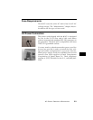
Connecting to a PC or Terminal