


6-48 Chapter 6: Programming
Model 801GC, 801GF & 801GX¥Rev. A
Most color displays that use separate RGB analog
video have separate sync inputs or expect sync added
to the green video input. The ASSG parameter speci-
fies which primaries output sync when analog com-
posite sync is selected. The current design of the
801G* only allows adding sync to the green output.
The only valid entries for ASSG are (0, 0, 0) and (0,
1, 0). In the case of monochrome displays that use
composite video and sync, the display must be con-
nected to the green output channel on the 801G*.
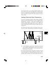
You will also need to specify the type of analog
composite sync signal that is to be generated. You
can specify a simple OR of the vertical and horizon-
tal pulses or a more elaborate sync signal consisting
of serrations and equalizing pulses. The ASCT com-
mand selects the exact type of sync that is added. A
setting of 0 means that analog composite sync can-
not be selected.
The ASSS parameter sets the peak-to-peak swing of
the sync portion of the composite analog video
waveform.
You can now skip the next two sections and go di-
rectly to the section on “Timing Parameters.”
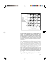
Digital Video Parameters
The current version of the 801G* firmware can gen-
erate five different types of digital video signals.
All of the outputs are at TTL levels. There are two
parameters that control the digital video configura-
tion of the 801G*. The DVST parameter selects from
the different types that are available. AVST must be
set to zero when digital video operation is selected.
The DVSP parameter specifys the logic sense (or
polarity) of the digital video outputs. The current
hardware configuration of the 801G* only supports
the active high (or positive) polarity.
All digital video displays require digital sync. In-
formation on setting the digital sync parameters is
presented in the next section.