


Chapter 3 73
Optimizing Performance
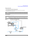
Creating and Applying User Flatness Correction
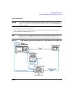
2. Configure the signal generator to interface with the power meter.
a. Press
Amplitude > More (1 of 2) > User Flatness > More (1 of 2) > Power Meter > E4416A, E4417A, E4418B,
or
E4419B.
b. Press
Meter Address > enter the power meter’s GPIB address > Enter.
c. For E4417A and E4419B models, press
Meter Channel A B to select the power meter’s active channel.
d. Press
Meter Timeout to adjust the length of time before the instrument generates a timeout error if
unsuccessfully attempting to communicate with the power meter.
3. Press
More (2 of 2) > Configure Cal Array > More (1 of 2) > Preset List > Confirm Preset.
This opens the User Flatness table editor and resets the cal array frequency/correction list.
4. Press
Configure Step Array.
This opens a menu for entering the user flatness step array data.
5. Press
Freq Start > 26.5 > GHz.
6. Press
Freq Stop > 40 > GHz.
7. Press
# of Points > 28 > Enter.
This enters the desired flatness-corrected frequencies (26.5 GHz to 40 GHz in 500 MHz intervals) into
the step array.
8. Press
Return > Load Cal Array From Step Array > Confirm Load From Step Data.
This populates the user flatness correction array with the frequency settings defined in the step array.
9. Press
Amplitude > 0 > dBm.
10. Press
RF On/Off.
This activates the RF output and the RF ON annunciator is displayed on the signal generator.
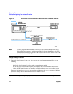
Perform the User Flatness Correction
NOTE If you are not using an Agilent E4416A/17A/18B/19B power meter, or if your power meter
does not have a GPIB interface, you can perform the user flatness correction manually. For
instructions, see Performing the User Flatness Correction Manually below.
1. Press
More (1 of 2) > User Flatness > Do Cal.
This creates the user flatness amplitude correction value table entries. The signal generator begins the
user flatness correction routine and a progress bar is shown on the display.