


Chapter 6 139
Custom Arb Waveform Generator
Working with Modulation Types
Creating a QPSK I/Q Modulation Type User File with the I/Q Values Editor
In I/Q modulation schemes, symbols appear in default positions in the I/Q plane. Using the I/Q Values
editor, you can define your own symbol map by changing the position of one or more symbols. Use the
following procedure to create and store a 4-symbol unbalanced QPSK modulation.
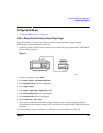
1. Press
Preset.
2. Press
Mode > Custom > Real Time I/Q Baseband > Modulation Type > Define User I/Q > More (1 of 2) >
Delete All Rows > Confirm Delete All Rows.
This loads a default 4QAM I/Q modulation and clears the I/Q Values editor.
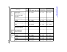
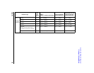
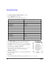
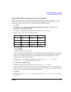
3. Enter the I and Q values listed in the following table:
a. Press
0.5 > Enter.
b. Press
1 > Enter.
c. Enter the remaining I and Q values.
As the I value updates, the highlight moves to the first Q entry (and provides a default value of 0) and an
empty row of data appears below the first row. As the Q value updates, the highlight moves to the next I
value. As you press the numeric keys, the numbers display in the active entry area. If you make a
mistake, use the backspace key and retype.
Also note that 0.000000 appears as the first entry in the list of Distinct Values, and that
0.500000 and 1.000000 are listed as the distinct values.
4. Press
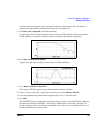
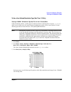
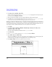
More (2 of 2) > Display I/Q Map.
An I/Q State Map is displayed from the current values in the I/Q Values table.
The I/Q State Map in this example has four symbols. The I/Q State Map uses the following four unique
values: 0.5, 1.0, −0.5, and −1.0 to create the four symbols. It is not the number of values that defines how
many symbols a map has, but how those values are combined.
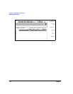
5. Press
Return.
When the contents of an I/Q Values table have not been stored, I/Q Values (UNSTORED) appears
on the display.
Symbol Data I Value Q Value
0 0000 0.500000 1.000000
1 0001 −0.500000 1.000000
2 0010 0.500000 −1.000000
3 0011 −0.500000 −1.000000