


Chapter 5 107
Dual Arbitrary Waveform Generator
Using Waveform Markers
To Toggle Markers As You Create a Waveform Sequence
You can combine waveform segments to create a waveform sequence while independently toggling the
markers of each waveform segment.
In this example, you learn how to toggle markers while building a waveform sequence. If you have not
created waveform segments, complete the steps in the previous section, “Creating Waveform Segments” on
page 100.
1. Press
Mode > Dual ARB > Waveform Sequences > Build New Waveform Sequence.
2. Press
Insert Waveform.
3. Highlight the desired waveform segment (for example, TTONE).
4. Press
Insert Selected Waveform > Insert Selected Waveform > Done Inserting.
5. Highlight the first waveform segment.
An entry (1, 2 or 12) in the Mk column indicates that a marker is active. No entry in that column means
that both markers are off.
6. Press
Toggle Markers.
7. Press
Toggle Marker 1 and Toggle Marker 2 until only 2 is showing in the Mk column.
8. Highlight the next waveform segment.
9. Press
Toggle Marker 1 and Toggle Marker 2 until both 1 and 2 are showing in the Mk column.
10. Press
Return.
You now have a waveform sequence that contains two TTONE waveform segments. Marker 2 is on for the
first waveform segment and markers 1 and 2 are on for the second waveform segment.
To Verify Marker Operation
In this example, you learn how to verify marker operation. If you have not created waveform segments and
applied makers, complete the steps in the previous sections, “Creating Waveform Segments” on page 100
and “To Place a Marker at the First Point within a Waveform Segment” on page 104.
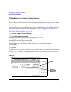
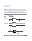
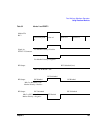
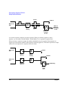
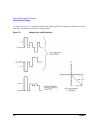
Once you set a marker on a waveform segment, you can detect the marker pulse at the EVENT 1 or EVENT
2 connectors (EVENT 1 for this example). For more information, see “Waveform Marker Concepts” on
page 108
1. Press
Mode > Dual ARB > Select Waveform.
2. Highlight the desired waveform segment or sequence.
3. Press
ARB Off On to On.
4. Connect an oscilloscope input to the EVENT 1 connector, and trigger on the Event 1 signal.
When a marker is present, a marker pulse is displayed on the oscilloscope.