


Chapter 5 91
Dual Arbitrary Waveform Generator
Arbitrary (ARB) Waveform File Headers
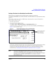
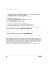
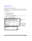
2. Save the information in the Current Inst. Settings column to the file header:
Press
Save Setup To Header.
The same settings are now displayed in both the Saved Header Settings column and the Current
Inst. Settings column. The settings in the Saved Header Settings column are the ones that
have been saved in the file header.
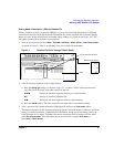
The following signal generator settings are saved to the file header:
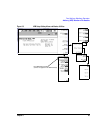
32-Character Description: A description entered for the header, such as a the waveform’s function (saved/edited
with the
Edit Description key, see Figure 5-2 on page 90).
Sample Rate: The ARB sample clock rate.
Runtime Scaling: The Runtime scaling value. Runtime scaling is applied in real-time while the
waveform is playing. This setting can be changed only for files in the dual ARB player.
Marker 1...4 Polarity: The marker polarity, positive or negative.
ALC Hold Routing: Which marker, if any, implements the PSG’s ALC hold function.
The ALC hold function holds the ALC modulator at its current level when the marker
signal is low. When the marker signal goes high, the ALC hold function is
discontinued. If the RF Blank Routing function is selected, it automatically activates
the ALC hold for the same marker.
Alt Ampl. Routing: Which marker, if any, triggers the PSG’s alternate amplitude feature when the marker
signal is low. When the marker signal goes high, the trigger is terminated disengaging
alternate amplitude. You must configure the alternate amplitude parameters, accessed
in the
Amplitude hardkey menu.
RF Blank Routing: Which marker, if any, implements the PSG’s RF blanking function when the marker
signal is low. Selecting RF blanking also implements ALC hold. When the marker
signal goes high, RF blanking is discontinued.
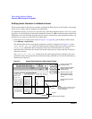
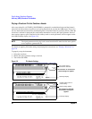
NOTE All waveforms generated in the PSG have a marker on the first sample point. To see the desired
results from the three routing selections, you may need to select a range of sample (marker)
points. To set the marker points, use the
Set Marker on Range of Points softkey in the Marker Utilities
menu. Refer to “To Place a Marker Across a Range of Points within a Waveform Segment” on
page 104 for more information.
I/Q Mod Filter: The I/Q modulator filter setting. The modulator filter affects the I/Q signal modulated
onto the RF carrier.
I/Q Output Filter: The I/Q output filter setting. The I/Q output filter is used for I/Q signals routed to the
rear panel I and Q outputs.
Mod Attenuation: The I/Q modulator attenuation setting.