


Chapter 1 21
Signal Generator Overview
Rear Panel
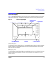
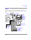
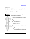
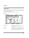
15. AUXILIARY I/O
This female 37-pin connector (E8267C only) is active only on instruments with an internal baseband
generator (Option 002/602); on signal generators without Option 002/602, this connector is non-functional.
This connector provides access to the inputs and outputs described in the following figure.
Figure 1-5 Auxiliary I/O Connector (Female 37-Pin)
Used with an internal baseband generator. This pin accepts a CMOS sign
al
for synchronization of external data and alternate power signal timing.
Damage levels are > +8V and < −4V.
View looking into
rear panel connector
Used with an internal baseband generator. This pin relays a
CMOS bit clock signal for synchronizing serial data.
Used with an internal baseband generator. This pin outputs data (CMOS)
from the internal data generator or the externally supplied signal at data in
put
Used with an internal baseband generator. In arbitrary waveform mode, this pin outp
ut
a timing signal generated by Marker 3. A marker (3.3V CMOS high when positive
polarity is selected; 3.3V CMOS low when negative polarity is selected) is output o
n
this pin when a Marker 3 is turned on in the waveform.
Reverse damage levels: > +8V and < −4V.
Accepts a signal that triggers an internal pattern or frame generato
r to
start single pattern output. Minimum pulse width: 100 ns.
Damage levels: > +5.5 and < −0.5V
Used with an internal baseband generator. This pin outputs the CMO
S
symbol clock for symbol synchronization, one data clock period wide
.
Used with an internal baseband generator. In arbitrary waveform mode, this
pin
outputs a timing signal generated by Marker 4. A marker (3.3V CMOS high
when positive polarity is selected; 3.3V CMOS low when negative polarity is
selected) is output on this pin when a Marker 4 is turned on in the waveform
.
Reverse damage levels: > +8V and < −4V.