


18 Chapter 1
Signal Generator Overview
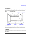
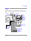
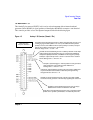
Rear Panel
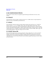
1. AC Power Receptacle
The ac line voltage is connected here. The power cord receptacle accepts a three-pronged power cable that is
shipped with the signal generator.
2. GPIB
This GPIB interface allows listen and talk capability with compatible IEEE 488.2 devices.
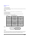
3. AUXILIARY INTERFACE
This 9-pin D-subminiature female connector is an RS-232 serial port that can be used for serial
communication and Master/Slave source synchronization.
Figure 1-4
4. LAN
This LAN interface allows ethernet local area network communication through a 10Base-T LAN cable. The
yellow LED on the interface illuminates when data transmission (transfer/receive) is present. The green
LED illuminates when there is a delay in data transmission or no data transmission is present.
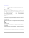
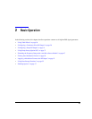
Table 1-3 Auxiliary Interface Connector
Pin Number Signal Description Signal Name
1 No Connection
2 Receive Data RECV
3 Transmit Data XMIT
4+5V
5 Ground, 0V
6 No Connection
7Request to SendRTS
8 Clear to Send CTS
9 No Connection
View looking into
rear panel connector