


Chapter 1 17
Signal Generator Overview
Rear Panel
Rear Panel
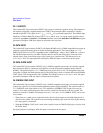
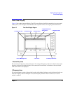
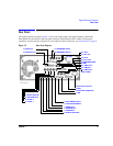
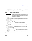
The signal generator rear panel (Figure 1-3) provides input, output, and remote interface connections.
Descriptions are provided for each rear panel connector. When Option 1EM is added, all front panel
connectors are moved to the real panel; for a description of these connectors, see “Front Panel” on page 6.
Figure 1-3 Rear Panel Diagram
3. AUXILIARY INTERFACE
2. GPIB
13. PATTERN TRIG
27. 10 MHz IN
26. 10 MHz OUT
12. EVENT 2
11. EVENT 1
4. LAN
1. AC Power Receptacle
28. 10 MHz EFC
(Option UNR)
14. BURST GATE IN
15. AUXILIARY I/O
16. Digital Bus
17. WIDEBAND I INPUT
18. WIDEBAND Q INPUT
20. I OUT
21. I-bar OUT
22. Q OUT
23. Q-bar OUT
24. BASEBAND GEN
8. TRIGGER OUT
9. TRIGGER IN
10. SOURCE SETTLED
7. SWEEP OUT
19. COH
5. STOP SWEEP IN/OUT
6. Z-AXIS BLANK/MKRS
25. SMI