


10 Chapter 1
Signal Generator Overview
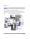
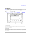
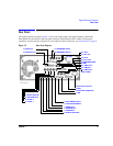
Front Panel
18. RF OUTPUT
This connector is the output for RF and microwave signals. The nominal output impedance is 50Ω. The
reverse-power damage levels are 0 Vdc, 0.5 watts nominal. On signal generators with Option 1EM, this
output is relocated to a rear panel female BNC connector.
19. SYNC OUT
This female BNC output connector (E8257C and E8267C only) outputs a synchronizing TTL-compatible
pulse signal that is nominally 50 ns wide during internal and triggered pulse modulation. The nominal
source impedance is 50Ω. On signal generators with Option 1EM, this output is relocated to the rear panel.
20. VIDEO OUT
This female BNC output connector (E8257C and E8267C only) outputs a TTL-level compatible pulse signal
that follows the output envelope in all pulse modes. The nominal source impedance is 50Ω. On signal
generators with Option 1EM, this output is relocated to the rear panel.
21. Line Power LED
This green LED indicates when the signal generator power switch is set to the on position.
22. Power Switch
In the on position, this switch activates full power to the signal generator; in standby, it deactivates all signal
generator functions. In standby, the signal generator remains connected to the line power and power is
supplied to some internal circuits.
23. Standby LED
This yellow LED indicates when the signal generator power switch is set to the standby condition.
24. Incr Set
This hardkey enables you to set the increment value of the current active function. This the increment value
of the current active function appears in the active entry area of the display. Use the numeric keypad, arrow
hardkeys, or the knob to adjust the increment value.
25. GATE/PULSE/TRIGGER INPUT
This female BNC input connector (E8257C and E8267C only) accepts an externally supplied pulse signal
for use as a pulse or trigger input. With pulse modulation, +1V is on and 0V is off (trigger threshold of 0.5V
with a hysteresis of 10%; so 0.6V would be on and 0.4V would be off). The damage levels are ±5V
rms
and