


172 Chapter 8
Multitone Waveform Generator
Creating, Viewing, and Optimizing Multitone Waveforms
The multitone signal should be available at the signal generator RF OUTPUT connector.
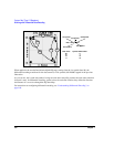
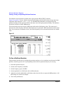
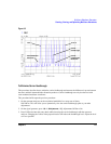
Figure 8-2 on page 172 shows what the signal generator display should look like after all steps have been
completed. Notice that the M-TONE, I/Q, RF ON, and MOD ON annunciators are displayed and the
parameter settings for the signal are shown in the status area of the signal generator display. The multitone
waveform is stored in volatile ARB memory.
The waveform has nine tones spaced 1 MHz apart with random initial phase values. The center tone is
placed at the carrier frequency, while the other eight tones are spaced in 1 MHz increments from the center
tone. If you create an even number of tones, the carrier frequency will be centered between the two middle
tones.
Figure 8-2
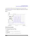
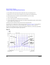
To View a Multitone Waveform
This procedure describes how to configure the spectrum analyzer to view a multitone waveform and its IMD
products. Actual key presses will vary, depending on the model of spectrum analyzer you are using.
1. Preset the spectrum analyzer.
2. Set the carrier frequency to 20 GHz.
3. Set the frequency span to 20 MHz.
4. Set the amplitude for a 10 dB scale with a 4 dBm reference.
5. Adjust the resolution bandwidth to sufficiently reduce the noise floor to expose the IMD products. A 9.1
kHz setting was used in our example.
6. Turn on the peak detector.