


190 Chapter 10
Troubleshooting
RF Output Power Problems
Signal Loss While Working with a Mixer
If you experience signal loss at the signal generator’s RF output during low-amplitude coupled operation
with a mixer, you can solve the problem by adding attenuation and increasing the RF output amplitude of the
signal generator.
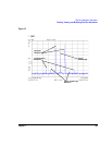
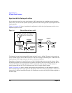
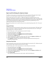
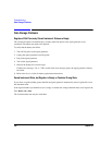
Figure 10-1 on page 190 shows a hypothetical configuration in which the signal generator provides a low
amplitude signal to a mixer.
Figure 10-1 Effects of Reverse Power on ALC
The internally leveled signal generator RF output (and ALC level) is -8 dBm. The mixer is driven with an
LO of +10 dBm and has an LO-to-RF isolation of 15 dB. The resulting LO feedthrough of -5 dBm enters the
signal generator’s RF output connector and arrives at the internal detector.
Depending on frequency, it is possible for most of this LO feedthrough energy to enter the detector. Since
the detector responds to its total input power regardless of frequency, this excess energy causes the ALC to
reduce the RF output of the signal generator. In this example, the reverse power across the detector is
actually greater than the ALC level, which may result in loss of signal at the RF output.
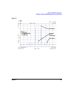
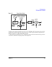
Figure 10-2 on page 191 shows a similar configuration with the addition of a 10 dB attenuator connected
between the RF output of the signal generator and the input of the mixer. The signal generator’s ALC level is
increased to +2 dBm and transmitted through a 10 dB attenuator to achieve the required -8 dBm amplitude at
the mixer input.
RF LEVEL
CONTROL
SIGNAL GENERATOR
OUTPUT CONTROL
MIXER
LO
IF
ALC LEVEL
= - 8 dBm
DETECTOR
MEASURES
- 8 dBm
ALC LEVEL
DETECTOR
MEASURES
- 5 dBm
REVERSE
POWER
LO FEEDTHRU
= - 5 dBm
RF OUTPUT
= - 8 dBm
LO LEVEL
= +10 dBm