


Chapter 3 63
Optimizing Performance
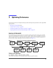
Using External Leveling
External Leveling with Option 1E1 Signal Generators
Signal generators with Option 1E1 contain a step attenuator prior to the RF output connector. During
external leveling, the signal generator automatically holds the present attenuator setting (to avoid power
transients that may occur during attenuator switching) as the RF amplitude is changed. A balance must be
maintained between the amount of attenuation and the optimum ALC level to achieve the required RF
output amplitude. For optimum accuracy and minimum noise, the ALC level should be greater than −10
dBm.
For example, leveling the CW output of a 30 dB gain amplifier to a level of −10 dBm requires the output of
the signal generator to be approximately −40 dBm when leveled. This is beyond the amplitude limits of the
ALC modulator alone, resulting in an unleveled RF output. Inserting 45 dB of attenuation results in an ALC
level of +5 dBm, well within the range of the ALC modulator.
NOTE In the example above, 55 dB is the preferred attenuation choice, resulting in an ALC level
of +15 dBm. This provides adequate dynamic range for AM or other functions that vary the
RF output amplitude.
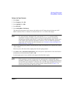
To achieve the optimum ALC level at the signal generator RF output of −40 dBm for an unmodulated
carrier, follow these steps:
1. Press
Amplitude > Set Atten > 45 > dB.
2. Press Set ALC Level > 5 > dBm.
This sets the attenuator to 45 dB and the ALC level to +5 dBm, resulting in an RF output amplitude of -40
dBm, as shown in the AMPLITUDE area of the display.
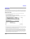
To obtain flatness-corrected power, refer to “Creating and Applying User Flatness Correction” on page 64.
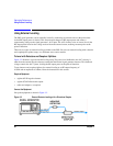
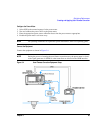
To Level with a mm-Wave Source Module
Millimeter-wave source module leveling is similar to external detector leveling. The power level feedback
signal to the ALC circuitry is taken from the millimeter-wave source module, rather than the internal signal
generator detector. This feedback signal levels the RF output power at the mm-wave source module output
through the signal generator’s rear panel SOURCE MODULE interface connector.
For instructions and setups, see “Extending the Frequency Range with a mm-Wave Source Module” on
page 47.