


108 Chapter 5
Dual Arbitrary Waveform Generator
Using Waveform Markers
Waveform Marker Concepts
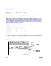
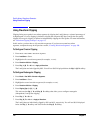
The Dual Arb mode of the signal generator has four markers that you can place on a waveform segment.
Marker 1 and Marker 2 provide auxiliary output signals to the rear-panel EVENT 1 and EVENT 2
connectors, respectively. Markers 3 and 4 are available only for custom-programmed waveforms, and they
provide auxiliary output signals to pins 19 and 18 of the rear-panel AUXILIARY I/O connector,
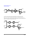
respectively. You can construct these output signals as a trigger signal to synchronize another instrument to a
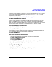
given portion of a waveform. The following timing diagrams describe the effects of Markers 1 and 2 on the
state of the signal at the EVENT 1 and EVENT 2 rear panel connectors.
NOTE If marker polarity selection is not be available in your version of the firmware, marker
polarity is always positive.
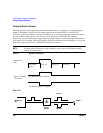
Figure 5-10
Table 5-1 Marker 1 and EVENT 1
Marker File
Bit 1
Waveform
point n
point n+1 point n+2 point n+3 . . .
Signal At EVENT
1 Connector
For Marker Polarity = Positive
For Marker Polarity = Negative
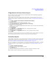
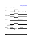
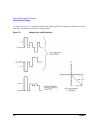
Marker File
Bit 1
Marker
Polarity
EVENT 1
Negative
Positive
±