


Chapter 2 29
Basic Operation
Configuring the RF Output
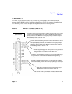
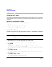
6. Press the up arrow key.
Each press of the up arrow key increases the frequency by the increment value last set with the
Incr Set
hardkey. The increment value is displayed in the active entry area.
7. The down arrow decreases the frequency by the increment value set in the previous step. Practice
stepping the frequency up and down in 1 MHz increments.
You can also adjust the RF output frequency using the knob. As long as frequency is the active function
(the frequency is displayed in the active entry area), the knob will increase and decrease the RF output
frequency.
8. Use the knob to adjust the frequency back to 700 MHz.
Setting the Frequency Reference and Frequency Offset
The following procedure sets the RF output frequency as a reference frequency to which all other frequency
parameters are relative. The frequency initially shown on the display is 0.00 Hz (the frequency output by
the hardware minus the reference frequency). Although the display changes, the frequency output does not
change. Any subsequent frequency changes are shown as incremental or decremental to 0 Hz.
1. Preset the signal generator: Press:
Preset
2. Set the frequency reference to 700 MHz:
Press:
Frequency > 700 > MHz > More (1 of 3) > Freq Ref Set.
This activates the frequency reference mode and sets the current output frequency (700 MHz) as the
reference value. The FREQUENCY area displays 0.000 Hz, which is the frequency output by the
hardware (700 MHz) minus the reference value (700 MHz). The REF indicator activates and the
Freq Ref Off On softkey toggles to On.
3. Turn on the RF output: Press
RF On/Off.
The display annunciator changes from RF OFF to RF ON. The RF frequency at the RF OUTPUT
connector is 700 MHz.
4. Set the frequency increment value to 1 MHz: Press
Frequency > Incr Set > 1 > MHz.
5. Increment the output frequency by 1 MHz: Press the up arrow key.
The FREQUENCY area display changes to show 1.000 000 000 MHz, which is the frequency output by
the hardware (700 MHz + 1 MHz) minus the reference frequency (700 MHz). The frequency at the RF
OUTPUT changes to 701 MHz.
6. Enter a 1 MHz offset: Press
More (1 of 3) > Freq Offset > 1 > MHz.
The FREQUENCY area displays 2.000 000 00 MHz, which is the frequency output by the hardware
(701 MHz) minus the reference frequency (700 MHz) plus the offset (1 MHz). The OFFS indicator
activates. The frequency at the RF OUTPUT connector is still 701 MHz.