Removal and Installation
8-82
HP DesignJet 5000 and 5500 Series Printers Service Manual
Removal
WARNING Switch off the Printer and remove the Power Cord.
NOTE Refer to the table on Page 8-4 for information on screw types.
1. Remove the LAN Card - Refer to
Page 8-76.
2. Remove the Left Rear Cover - Refer
to Page 8-15.
3. Remove the Right Rear Cover - Refer
to Page 8-16.
4. Remove the Electronics Module
Cover - Refer to Page 8-79.
5. Disconnect and remove the Hard Disk
Drive for safety reasons - Refer to
Page 8-74.
6. Remove ALL Firmware/Memory
DIMMs - Refer to Page 8-77.
NOTE 0DNHVXUH\RXUHLQVWDOOWKH
)LUPZDUH0HPRU\ ',00V
RQWKHQHZ0DLQ3&$
7. Disconnect ALL Cables from the
Electronics Module.
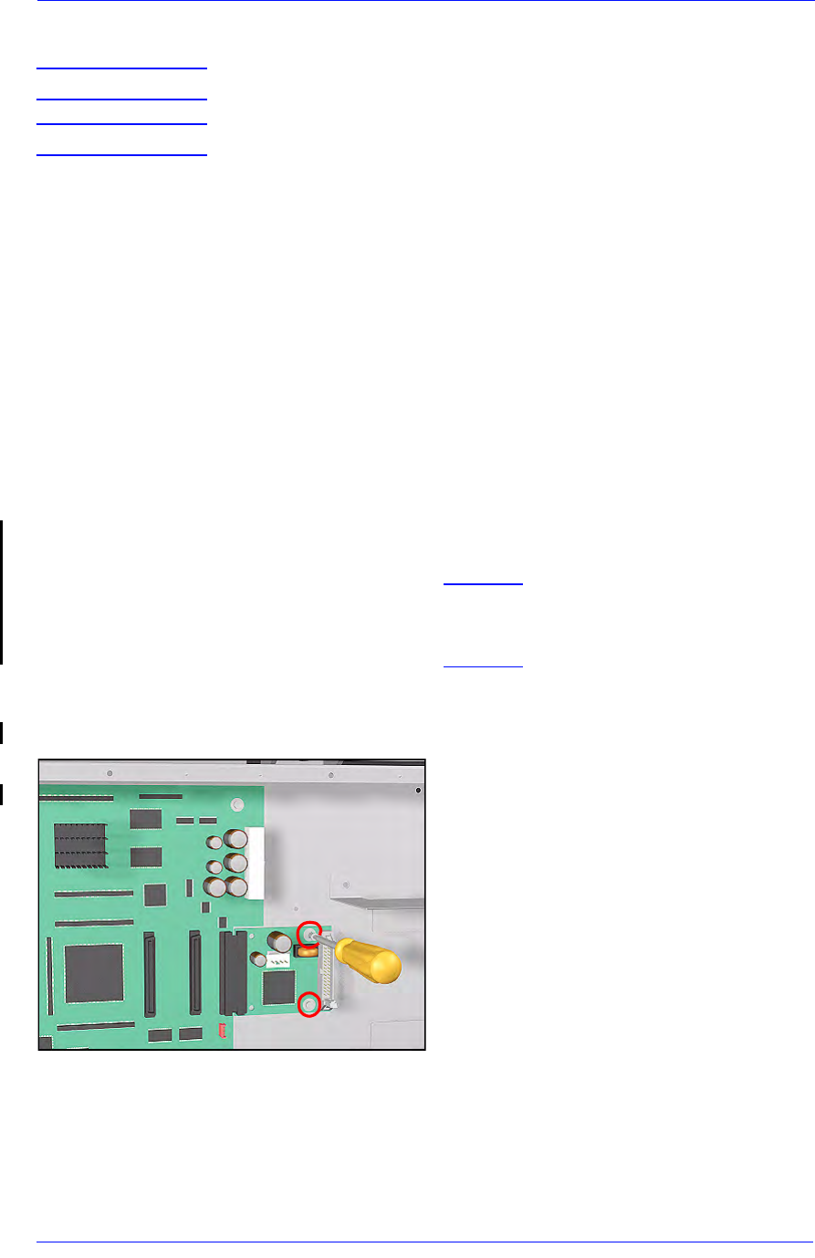
8. Remove 2 T-10 screws (Type K) to
remove the PCI-to-IDE PCA.


